Network Functions
®
68
SECTION 7
DriveRack
™
Since a DriveRack™ network system can be so very detailed with a tremendous amount of infor-
mation being transmitted across the network backbone, the following information is provided
to aid you in the unfortunate event that you have network communication problems in your
DriveRack™ system.
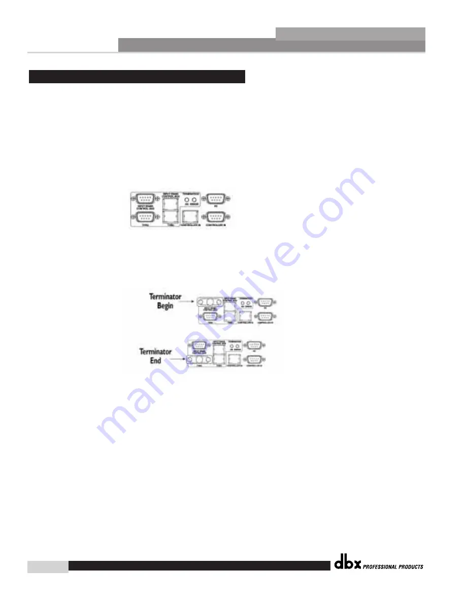
Termination Indicators - OK or ERROR
- The best place to begin network troubleshooting,
is with the Termination indicators located on the back panel of the DriveRack™ units. The
Green LED indicates that network termination is working. The Red LED indicates that there is
an error in the network termination. They will appear as follows:
Terminator Connectors-
When multiple DriveRack™ units are used in a network system,
make certain that the included terminator plugs are connected properly at the input bus of the
master unit and the thru bus on the last unit in the network as the following illustration
indicates:
Identification numbers
- It is of paramount importance that any unit within a DriveRack™
network system have a unique ID number assigned. In addition, there can be only one
master unit assigned for the network to function properly.
Utility Configure Network Page Display -
When a DriveRack™ network is established, page
one of the utility menu will show all device ID number currently in the DriveRack™ network
system.
Network Cables -
Make sure to check all cable types and connectors.
PC Cable -
When running from the DriveRack™ to and from the PC, it is required that a null
modem cable be used.
dbx Professional Products Customer Service -
In the unfortunate event that networking
problems persist, please contact us directly at: 801.568.7760 or on-line at: [email protected].
7.5 Network Trouble Shooting
DriveRack™ User Manual
Summary of Contents for DriveRack 480
Page 1: ...User Manual CompleteEqualization LoudspeakerManagementSystem 480 481 482 480R...
Page 6: ...INTRO CUSTOMER SERVICE INFO Defining the DriveRack WARRANTY INFO INTRODUCTION DriveRack...
Page 11: ...Getting Started Section 1 DriveRack...
Page 19: ...EDITING FUNCTIONS Editing Functions Section 2 DriveRack...
Page 23: ...2 5 Navigating the EQ Sections Editing Functions Section 2 DriveRack 13 DriveRack User Manual...
Page 24: ...Editing Functions 14 Section 2 DriveRack 2 6 Navigating the XOVER DriveRack User Manual...
Page 25: ...2 7 Navigating the RTA Editing Functions Section 2 DriveRack 15 DriveRack User Manual...
Page 26: ...Editing Functions 16 Section 2 DriveRack 2 8 Navigating the Delay DriveRack User Manual...
Page 30: ...CONFIGURATION FUNCTIONS SOFTWARE Section 3 DriveRack...
Page 40: ...DETAILED PARAMETERS PARAMETERS Section 4 DriveRack...
Page 52: ...STORING PROGRAM CHANGES Storing Programs Section 5 DriveRack...
Page 56: ...UTILITIES SECTION Utilities Section 6 DriveRack...
Page 66: ...NETWORK FUNCTIONS Network Functions DriveRack...
Page 82: ...480R Remote Controller Section 8 DriveRack...
Page 90: ...APPLICATION GUIDE Section 9 DriveRack...
Page 97: ...Appendix DriveRack...
Page 114: ...DriveRack User Manual 106 Appendix A DriveRack A 9 Input and Output Diagrams...


