background image

®

Configuring the DriveRack™

Section 3

DriveRack

25

DriveRack™ User Manual

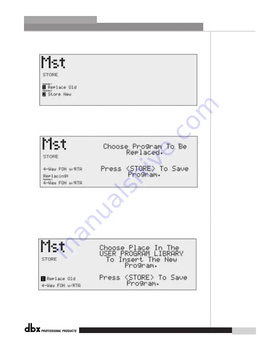
• Once you are satisfied with the selected name press, the 

STORE

button again and the

screen will appear something like this:

• If you wish to replace an existing User program, press the 

PARAMETER 1

knob and the

display will appear as follows:

•  Use the 

Parameter 3

knob to select the USER program to be replaced.  Once the pro-

gram to be replaced has been selected, press the 

STORE

button once again and the

program will then be replaced.

•  To store a program as a new USER program, press the 

STORE

button and then press

the 

Parameter 2

knob to store as new and the display will appear as follows:

• At this point, use the 

Parameter 2

knob to select the position where the new USER pro-

gram will be stored.

Summary of Contents for DriveRack 480

Page 1: ...User Manual CompleteEqualization LoudspeakerManagementSystem 480 481 482 480R...

Page 2: ...WHEN SWITCH IS IN THE OFF POSITION The cores in the mains lead are coloured in accordance with the following code GREEN and YELLOW Earth BLUE Neutral BROWN Live As colours of the cores in the mains le...

Page 3: ...evice may not cause harmful inter ference and this device must accept any interference received including interference that may cause undesired operation Operation of this unit within significant elec...

Page 4: ...ssovers 29 3 8 Saving Configuration Changes 30 Section 4 Detailed Parameters 4 1 Input Routing 32 4 2 1 Pre Crossover EQ 31 Band Graphic 32 4 2 2 Pre Crossover EQ 31 Band Graphic Show and House 33 4 2...

Page 5: ...y FOH 82 9 2 Front of House w Delay 3 Way Towers 83 9 3 L C R Sub Rear 84 9 4 Bi Amp In Ear 85 9 5 Dedicated FOH Crossover 86 9 6 Stand Alone Monitor EQ 87 Section 10 Appendix A 1 MIDI SYSEX 90 A 2 Fa...

Page 6: ...INTRO CUSTOMER SERVICE INFO Defining the DriveRack WARRANTY INFO INTRODUCTION DriveRack...

Page 7: ...ng The following are just some of the features of the 480 481 482 and 480R 480 DriveRack features 4 Input and 8 Outputs with routing 31 band graphic or 9 band parametric equalizer on every input pre c...

Page 8: ...nd Transducer Alignment Delays Compressor Limiter on every output Speaker Compensation EQ post crossover Multi level Security System Separate House and Show EQ with individual lockouts Triple redundan...

Page 9: ...mber of your unit this is printed on a sticker attached to the rear panel If you have not already taken the time to fill out your warranty registration card and send it in please do so now Before you...

Page 10: ...ny consequential damage as a result of the product s use in any circuit or assembly 4 dbx reserves the right to make changes in design or make additions to or improvements upon this product without in...

Page 11: ...Getting Started Section 1 DriveRack...

Page 12: ...on to other units in the DriveRack net work link RS485 Control Bus Input RJ 45 connector type This input network connection is used to receive information being sent from other units in the DriveRack...

Page 13: ...isplay The large LCD display of the 480 DriveRack provides the user with all of the vital processing information of the DriveRack including signal routing configuration modes effect block edit ing and...

Page 14: ...user with eight independent 12 seg ment Lightpipe output meters that range from 30 to 22 dBu Note These meters are calibrated for the 22dBu setting of the gain jumpers Output Mutes The eight output m...

Page 15: ...Rack offers eight electronically balanced Euroblock con nectors Inputs 1 4 The input section of the 481 DriveRack offers four electronically balanced Euroblock con nectors Ground Lift Switch This swit...

Page 16: ...es the user with eight independent 6 segment lightpipe output meters that range from 30 to 22 dBu Note These meters are calibrated for the 22dBu setting of the gain jumpers Power Switch Turns the 481...

Page 17: ...ormation to and from the GUI interface Outputs 1 8 The output section of the 482 DriveRack offers eight electronically balanced XLR connectors Inputs 1 4 The input section of the 482 DriveRack offers...

Page 18: ...the 480R PC LED This LED when lit indicates that the 482 is connected to the PC When it is flashing the 482 is sending receiving information from the PC Input Meters The 482 provides the user with fou...

Page 19: ...EDITING FUNCTIONS Editing Functions Section 2 DriveRack...

Page 20: ...lly three different modes of navigation when per forming programming edits 1 FX buttons This array of 12 FX buttons is your primary mode of accessing any effect module 2 NEXTPG PREVPG page buttons Suc...

Page 21: ...Limiter effect menu Successive presses will move through the dynamics modules OTHER Selects the Input and Output editing sections of the DriveRack PROGRAM CONFIG This button will load a selected prog...

Page 22: ...ation feature which helps streamline navigation and editing of the unit The Horizontal Vertical Navigation mode allows the user to use the parameter knobs 2 3 to quickly navigate through the program c...

Page 23: ...2 5 Navigating the EQ Sections Editing Functions Section 2 DriveRack 13 DriveRack User Manual...

Page 24: ...Editing Functions 14 Section 2 DriveRack 2 6 Navigating the XOVER DriveRack User Manual...

Page 25: ...2 7 Navigating the RTA Editing Functions Section 2 DriveRack 15 DriveRack User Manual...

Page 26: ...Editing Functions 16 Section 2 DriveRack 2 8 Navigating the Delay DriveRack User Manual...

Page 27: ...2 9 Navigating the Dynamics Section Editing Functions Section 2 DriveRack 17 DriveRack User Manual...

Page 28: ...Editing Functions 18 Section 2 DriveRack 2 10 Navigating the Other Section DriveRack User Manual...

Page 29: ...2 11 Navigating the Utility Section Editing Functions Section 2 DriveRack 19 DriveRack User Manual...

Page 30: ...CONFIGURATION FUNCTIONS SOFTWARE Section 3 DriveRack...

Page 31: ...p the conventional program and that they are all unique to each individual program The utility menu mode and Network setup and management and setup are accessed via the utility menu and are not part o...

Page 32: ...put which utilizes an EQ type module X OVER Crossover s and filters RTA Real Time Audio Analyzer DELAY Delay and Driver Alignment Delay successive presses will you move through each input and output w...

Page 33: ...module in edit mode Once you are satisfied with the changes that have been made to a factory or user program the DriveRack allows you to save these changes to the program as a custom USER program by...

Page 34: ...splay will appear as follows Use the Parameter 3 knob to select the USER program to be replaced Once the pro gram to be replaced has been selected press the STORE button once again and the program wil...

Page 35: ...to the module that you wish to edit by using the PARAMETER 2 knob to move the cursor left and right and use the PARAMETER 3 knob to move the cursor up and down Once you have reached the module that y...

Page 36: ...move to the selected input of Notch filter section Once you are there use the PARAMETER 1 knob to select the desired Notch filter 3 5 D Delay Section The DriveRack units offer two unique delay section...

Page 37: ...In addition to output routing each output section of the DriveRack unit offers phase compensation within the selected output module The DriveRack provides the user with an option to link like modules...

Page 38: ...n You also have the ability to change the crossover output route while you are selecting and moving crossovers The procedure is as follows From Program mode press and hold the PROGRAM CONFIG button un...

Page 39: ...between select fx and route Xover Repeat this procedure to add additional and output route crossovers Once changes have been made to the current Configuration changes can be saved by pressing the NEX...

Page 40: ...DETAILED PARAMETERS PARAMETERS Section 4 DriveRack...

Page 41: ...arameter is used to adjust the level for the selected channel Master level Inf to 20dB Mixer module This parameter is used to control the overall output level of the mixed input signals High Pass Off...

Page 42: ...er flattens the GEQ or restores the GEQ to its original shape Frequency 20Hz to 20kHz This parameter allows you to select any one the 31 available frequencies Level 12 to 12 dB This parameter allows y...

Page 43: ...the slope of the high shelf parametric EQ Level 9 12 to 12 dB Sets the overall gain of the high shelf parametric EQ 4 2 4 REAL TIME ANALYZER RTA The DriveRack units offer two built in Real Time Audio...

Page 44: ...the selected notch filter Set to 6dB to help find unwanted feedback then set to 3dB to 36dB to remove Each input channel of the 480 481 and 482 DriveRack units offer a room channel delay effect The c...

Page 45: ...eters are available with various Crossovers A complete diagram of each crossover used in the 480 481 and 482 DriveRack units can be found in section A 7 of the Appendix 4 5 1 1X1 2X2 3X3 4X4 FILTERS F...

Page 46: ...er frequency Type Butterworth BW Bessel and Linkwitz Riley L R Selects the desired crossover filter type Low Slope 6 24dB Octave BW Bessel 12 48dB Octave L R Sets the Lowpass slope of the crossover fi...

Page 47: ...el 12 48dB Octave L R Sets the Highpass slope of the crossover filter 4 5 5 4 BAND CROSSOVERS 1X4 2X6W DUAL SUB 2X7 2X8 3X7W DUAL SUB 3X8 W DUAL SUB Low Fc 1 20Hz to 20kHz Selects the desired Lowpass...

Page 48: ...f the crossover filter High Slope 3 6 24dB Octave BW Bessel 12 48dB Octave L R Sets the Highpass slope of the crossover filter In addition to the pre crossover EQ options within the signal path the 48...

Page 49: ...for the Compressor Limiter are as follows and are user adjustable Compressor On Off Turns the compressor limiter module on and off Peakstop On Off This parameter turns the peakstop limiting on and of...

Page 50: ...old A 2 1 ratio means that if the incoming signal is 2dB over the thresh old the 480 481 and 482 DriveRack units will compress the signal and outputs a signal that only goes 1dB over the threshold For...

Page 51: ...plete output signal routing diagram Level Shift On Off This parameter is used to turn the selected output level and shift parameters on or off When level shift is off level is set to 0dB and phase is...

Page 52: ...STORING PROGRAM CHANGES Storing Programs Section 5 DriveRack...

Page 53: ...user program the DriveRack allows you to save these changes to save the program as a custom USER program by simply pressing the STORE button and the display will appear something like this Rotate the...

Page 54: ...gram will then be replaced To store a program as a new USER program press the STORE button and then press the PARAMETER 2 knob to store as new and the display will appear as follows At this point use...

Page 55: ...sfied with your Configuration changes press the NEXT PG button If you wish to abort press the PREV PG button and the DriveRack will return to Configuration mode Note that if you press the NEXT PG butt...

Page 56: ...UTILITIES SECTION Utilities Section 6 DriveRack...

Page 57: ...l of all other units can be performed by the master unit It is important to note that there can be only one unit designated as the master For more information on the networking capa bilities of the Dr...

Page 58: ...ions You can now proceed to set your operating security password This Password High or Med will allow you to prevent any unwanted users from manipulating operating parameters and functions of modules...

Page 59: ...y user Since the security system has three levels high med low there can be three different levels of users accessing the unit The high security password user can change lockout all modules and users...

Page 60: ...ply press PROGRAM to exit The 480 481 and 482 DriveRack units allow you to create custom program lists from within the Utility menu This list makes it for convenient accessing and grouping selected pr...

Page 61: ...either the conventional pro gram mode or by using the custom program list which was covered in section 6 5 By setting this option to Program List you now have the convenience of using only your select...

Page 62: ...ke this Use the PARAMETER 1 knob to set the desired display contrast The DriveRack will allow you to select the PC communication mode of either MIDI or RS 232 Using this option gives you the ability t...

Page 63: ...ER 3 button MIDI CH Selects which MIDI channel the 480 481 482 or 480R will receive program changes on Selections are OFF 1 16 or OMNI SYSEX ID Selects the SYSEX ID for the currently selected DriveRac...

Page 64: ...482 DriveRack units allow you to assign unique SYSEX ID numbers to an indi vidual unit The procedure for SYSEX ID setting is as follows Enter the Utility menu by pressing the UTILITY button once Press...

Page 65: ...unit For more information about Redundancy please refer to section 7 4 To enable this feature use the following procedure Enter the Utility menu by pressing the UTILITY button once Press the NEXT PG o...

Page 66: ...NETWORK FUNCTIONS Network Functions DriveRack...

Page 67: ...o col through a back bone system Use this section to optimize communication performance between networked DriveRacks Network Overview The following illustration shows the versatility of a DriveRack ne...

Page 68: ...eet RS 232 PC to any slave unit Max 50 feet MAXIMUM BACKBONE CABLE LENGTH 4000 feet Please See Section A 11 for Wire Diagram Information Connectors Every product in the DriveRack line feature both DB...

Page 69: ...ti ple unit network configuration communicate through a Back bone type connection This allows the units to transmit and receive information immediately through the line instead of the con ventional da...

Page 70: ...or 480R utilization Note that when you are making network connections using the 480R that you must first con nect the 480R to the included 480P This is required because not only does this connection e...

Page 71: ...e PC Once the master unit has been established access to all other units within the network system can be controlled via the PC The following illustra tion shows how to establish connection from the P...

Page 72: ...he ending of the Back bone network The following illustration indicates that the first termination connector be placed in the DB 9 control bus input of the first unit in the Back bone network system U...

Page 73: ...80 DriveRack From program mode press the UTILITY button and use the PREV PG and NEXT PG buttons to move to page 1 of the Utility menu The display will appear At this point use the PARAMETER 1 knob to...

Page 74: ...s utility menu where you will proceed to set IDs for networked units Controlling Remote Units In a DriveRack system the entire system can be controlled by either the 480 480R or the PC GUI interface T...

Page 75: ...is procedure anytime you wish to call up another device in the Network system via the 480 R DriveRack The procedure for calling up and controlling slave units using the 480R Remote Controller is quite...

Page 76: ...and then using the NEXTPG and PREVPG buttons to move to page 11 of the utility menu Use the PARAMETER 1 knob to engage the Redundancy Mode The display will now appear as follows At this point the mas...

Page 77: ...rminator plugs are connected properly at the input bus of the master unit and the thru bus on the last unit in the network as the following illustration indicates Identification numbers It is of param...

Page 78: ...means that when the GUI is in use any other device that uses the RS232 COMM port must be turned off INSTALL Install the DriveRack GUI interface from either the dbx Professional Products website at www...

Page 79: ...hat is currently setup to operate in the Network To edit any unit in the network select the desired unit with the mouse and double click To adjust the utility menu features of any unit in the network...

Page 80: ...view simply double click on the unit icon and a display screen will appear as follows At this point you can either use the mouse or the arrow keys to move to any one of the module blocks that you wis...

Page 81: ...face of the DriveRack GUI allows you to make selections to any parameter of any unit all in real time When there are many windows open for several units in the DriveRack network note that each window...

Page 82: ...480R Remote Controller Section 8 DriveRack...

Page 83: ...80R with other units in a Network environment DB 9 and RJ 45 Connectors Either of these connectors can be used to send and receive information from other DriveRack units in the network system via the...

Page 84: ...eRack including signal routing network device ID configuration modes effect block editing and RTA displays Function Buttons The function buttons of the 480R DriveRack allow access to all editing and n...

Page 85: ...The SYSTEM mute button when pressed and lit is used to mute all eight outputs of the select ed DriveRack unit To activate system mute press and hold for several seconds Hot Key Instant Access buttons...

Page 86: ...he DB 9 connector Cable lengths 480R to 480P 300 feet max 500 feet with dbx proprietary cable RS485 Link to Network Master RJ 45 connector type This connector is used to connect the 480R to the networ...

Page 87: ...LOCAL NETWORK SELECTION Always make certain that you are working on either the Network or the 480R s RTA by selecting LOCAL 1 or NETWORK 2 when you initially enter Utility mode Local indicates that yo...

Page 88: ...be made to the 480R itself The 480R allows you to instantly call up other devices in the DriveRack network by utilizing the exclusive Network keypad located on the front panel LOCAL NETWORK SELECTION...

Page 89: ...480R Remote Controller 80 Section 8 DriveRack Repeat the previous procedure when you wish to call up another device in the system DriveRack User Manual...

Page 90: ...APPLICATION GUIDE Section 9 DriveRack...

Page 91: ...Rack 4 Connect the optional 480R to the DriveRack via the network connector 5 Making sure that all outputs are muted apply power to the mixer and amplifiers Software 1 From Program Config mode select...

Page 92: ...ed apply power to the mixer and amplifiers Software 1 From Program Config mode select the desired configuration by using the PARAMETER 1 knob to scroll through the Program Configuration menu For more...

Page 93: ...om Program Config mode select the desired configuration by using the PARAMETER 1 knob to scroll through the Program Configuration menu For more information on config uration procedures please see sect...

Page 94: ...tware 1 From Program Config mode select the desired configuration by using the PARAMETER 1 knob to scroll through the Program Configuration menu For more information on config uration procedures pleas...

Page 95: ...DriveRack units and run to the selected speaker amplifier 3 Make network connections between the DriveRack 4 Connect the optional PC GUI to the DriveRack 1 via the front panel connector 5 Making sure...

Page 96: ...g mode select the desired configuration by using the PARAMETER 1 knob to scroll through the Program Configuration menu For more information on config uration procedures please see section 3 2 From Pro...

Page 97: ...Appendix DriveRack...

Page 98: ...ommands a split byte format is adopted for all data communication in this SYSEX implementation dd n 2 denotes the 1st through 7th bits of the nth byte and dd n 1 denotes th 8th bit of the nth byte Not...

Page 99: ...received n is different for each program If the 480 is sent a Receive One program procedure where the program number is not a valid RAM destination it will be ignored Receive Bulk Dump 48h SYS_HEAD 4...

Page 100: ...76 00 62 00 20 00 32 00 3A 00 47 00 74 00 52 00 76 Null to indicate end of Character String 00 00 Misc Setup Data too dynamic to document 00 07 00 00 00 06 00 00 00 03 00 06 00 03 00 32 00 08 00 03 00...

Page 101: ...abort the Factory Reset sequence and the unit will reset normally 481 and 482 Factory Soft Reset Press and Hold the ID UP button on power up until the following message appears in the 7 Seg Display SO...

Page 102: ...Download Session Front Panel 480 and 480R Press and hold the PREV PAGE button on power up until the following message appears WAITING FOR FLASH DOWNLOAD At this point follow the flash download instruc...

Page 103: ...ighted 22kHz BW Sample Rate 48kHz A D Wordlength 24 bits D A Performance Dynamic Range 112 dB unweighted 115 dB A weighted Sample Rate 48kHz D A Wordlength 24 bits System Performance Internal Wordleng...

Page 104: ...32 Power Requirements Watts 100 240V 50 60 Hz 35 Watts Dimensions Dimensions Height 3 5 X Width 19 X Depth 12 15 Weight 11lbs Shipping Weight 12 5lbs Specifications 481 DriveRack Inputs Inputs 4 Conne...

Page 105: ...utterworth or Bessel filters 12 24 36 or 48 dB octave for Linkwitz Riley filters Post EQ Type Parametric Number 4 EQ bands per output channel Range 15 dB range Dynamics Type Compressor Limiter with Pe...

Page 106: ...z BW 119 dB typical with program material A weighted 22kHz BW Sample Rate 48kHz A D Wordlength 24 bits D A Performance Dynamic Range 112 dB unweighted 115 dB A weighted Sample Rate 48kHz D A Wordlengt...

Page 107: ...5 lbs Specifications 480R Remote Controller DriveRack Inputs Number of Inputs 1 Real Time Audio Analyzer with switchable 48V phantom power Connectors Female XLR Type Electronically balanced RF filter...

Page 108: ...P HP 1X2 2 band 2X2 1 band HP H L LP 1X3 3 band 1X4 4 band Dual Filter 1 band HP H BP LP M L 2X3 2 band HP H HP LP H Sub L R L R L R HP H BP BP MH ML LP L 2X4 2 band HP H HP LP H L LP L H L 2X4 w sub...

Page 109: ...Sub Sub Sub 2X7 4 band HP H HP BP BP BP BP LP H MH MH ML ML Sub 2X8 4 band HP H HP BP H MH BP BP BP LP LP MH ML ML L L HP High Pass Filter BP Band Pass Filter LP Band Pass Filter L R L R L R L R L R...

Page 110: ...P HP BP LP H H Sub Sub Sub 3X6 w Sub 3 band HP H HP BP BP HP H M M HM LP Sub H H H M M M Sub 3X7 3 band HP HP HP BP BP BP LP 3X4 2 band HP H HP HP LP H H Sub 3X3 1 band LP HP BP LP HP BP LP HP BP HP H...

Page 111: ...w dual subs HP H HP BP BP HP H M M H M BP Sub LP Sub Sub 3X8 w dual subs 3 band HP HP HP BP BP BP BP LP 4X4 1 band LP HP BP LP HP BP LP HP BP LP HP BP HP High Pass Filter BP Band Pass Filter LP Band P...

Page 112: ...DriveRack User Manual 104 Appendix A DriveRack 4X8 2 band HP H HP HP H H HP LP LP H L L LP LP L L HP High Pass Filter BP Band Pass Filter LP Band Pass Filter...

Page 113: ...0 and 482 the top board must be removed 5 Once the desired settings have been made replace the chassis lid 481 T op Board Input Jumpers Output Jumpers 22dBu Ch1 30dBu 30dBu Ch1 Ch2 Ch1 Ch2 14dBu Ch2 1...

Page 114: ...DriveRack User Manual 106 Appendix A DriveRack A 9 Input and Output Diagrams...

Page 115: ...the Mic pre set up From program mode use either the OTHER or PARAMETER 2 and 3 buttons to move to the inputs which are sending signal to your speakers Once you have reached the desired inputs use the...

Page 116: ...Standard NUL modem Cable Note For using remote control cables longer than 250 feet use the following wire configuration 1 2 3 4 5 6 7 8 9 1 2 3 4 5 6 7 8 9 DB 9 Male DB 9 Male No Connect No Connect 1...

Page 117: ...andy Utah 84070 Phone 801 568 7660 Fax 801 568 7662 Int l Fax 219 462 4596 Questions or comments E mail us at customer dbxpro com or visit our World Wide Web home page at www dbxpro com A Harman Inter...

Reviews: