CBT36K Assembly Manual
Page
62
of 89
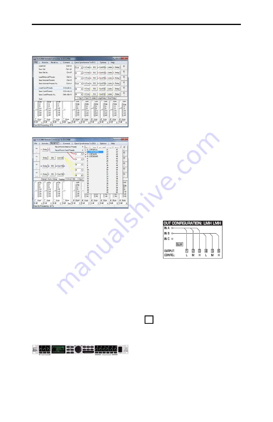
Now recall one of the crossover setups.
The crossover’s “live” settings will be set up
according to the choice you made. It is a good
idea to store this setting to one of the internal
memories in the crossover. Press [STORE] and
select an internal [INT] memory location by
using the [PARAM>] key and [KNOB]. Enter the
characters for the name but rotating the [KNOB]
in the [NAME] field.
Now proceed to section 12.2 “Connect the
Behringer DCX2496 Crossover to the System”
and also refer to section 13.2 “System
Connections: Example…...” to connect the
crossover to the amplifiers.
12.1.10. Load Settings Via Manual Entry with
Knobs on Front of DCX2496:
Manual entry is not difficult, but it is very tedious
and requires that you become familiar with the
menus of the DCX2496. Refer to the DCX2496
manual for details on the user interface.
12.1.10.1. DCX2496 User Interface Overview:
The front panel photo shown previously in Fig.
17 (repeated here for easy access) shows the
input and output channels.
On the far left are the input keys, these inputs
are identified as A, B and C but may be labeled
with more meaningful names such as LEFT or
RIGHT. When you press one of the input keys
the display will show 1 of 5 possible pages, you
can cycle through all of these pages by pressing
either the [<PAGE] or [PAGE>].
Once you move to the page that requires
modification you will use the [<PARAM] or
[PARAM>] to move between input fields on that
page (some pages only have one input field and
in this case the [PARAM] key is inactive). After
you navigate to the page and the field that
requires change, you will rotate the knob to
select the value needed.
Output channels are identified as 1, 2, 3, 4, 5,
and 6 but each channel can be labeled with a
more meaningful name such as SUB, MID and
HIGH. When you press one of the output keys
the display will show 1 of 8 possible pages.
Navigation to a specific field is accomplished the
same way as for the input channels using the
[PAGE], [PARAM] and [KNOB].
Other keys you will need are [MUTE] [RECALL]
[SETUP] [SUM], you can explore the other
functions after the speaker is up and playing.
The [COMPARE] feature is very handy for
comparing two different settings on the
crossover. [MUTE] allows you to mute the output
of any channel or any combination of channels.
Press [MUTE] followed by the channel you wish
to enable or disable.
12.1.10.2. Manual Crossover Setup Steps
We will set up each section step by step to help
you minimize entry errors. First, we need to set
the DCX2496 to a known state by resetting it to
its factory condition. This will automatically load
preset one which is a stereo-in three-channel-
out configuration (called LMH LMH by
Behringer). This is shown in the following
diagram from Behringer’s DCX2496 manual.
This preset links both stereo channels to allow
parameters to be entered in one channel only
rather than twice in both left and right channels.
Follow the sequence that follows and the
crossover will be ready to use once you
complete all the steps.
12.1.10.3. Step One, Set the Crossover to a
Known State; Reset to Factory
Condition:
In this step we are going to set the
crossover to a known state by restoring the
DCX2496 to its “shipped-from-the-factory” state
with all factory presets restored and all edited or
entered user presets erased.
If you’re working with a new DCX2496 for the
first time, you won’t have to worry about erasing
any of your presets. If your unit is not new
and/or you have used it before, you will have to
either store your presets on a compact flash
card or on your computer via a RS232 serial
connection before resetting.
Download the DCX2496 setup file from http://
www.parts-express.com/cbt36k-line-array-speaker-
pair-kit--301-980 and load it into the editor by
choosing [FILE] [LOAD CARD PRESETS]


