Datasat RS20i Installation And Operating Manual Download Page 48


RS20i Installation and Operating Guide 

 Page 48 


RS20i Installation & Operating Guide  

Document # 9301H52900 Ver. 1.00 

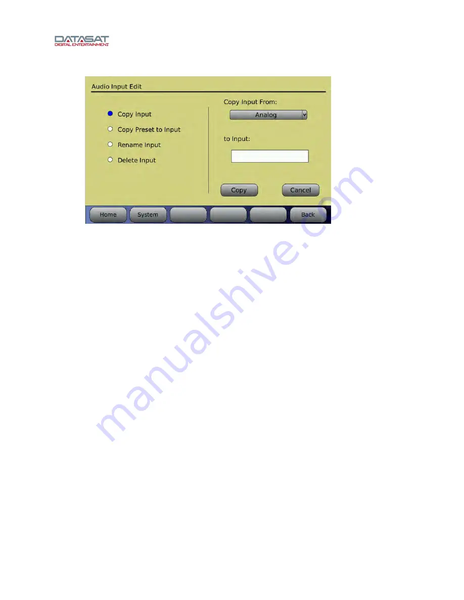
Setup (System) > Inputs > Edit Inputs > Copy Input 


Figure 29. Audio Input Edit, Copy Input 

For details about Copy Preset to Input, see 2.8.1 

Preset Inputs

, page 35. 


2.15  Using Dirac Live to Tune the Theater 

See the 

Dirac Live


Theater Setup Guide

 for detailed instructions.  The Dirac Live application is a 

separate tool, available from Datasat Digital Entertainment but not supplied with the RS20i processor.  

2.16  RS20i Playback Sound Check 

After installing and setting up the unit—or doing a maintenance check—it is a good idea to 
play content and stand in the theater while listening to the first few minutes of the movie.  
Check for the following 

ƒ


The overall sound level is comfortable and balanced. 

ƒ


The soundtrack quality is excellent and does not include extraneous noise. 

ƒ


The dialog is in sync with the picture being projected. 

ƒ


The surround speakers are heard at the correct level (Please note that not all scenes will 
have surround material.) 

To adjust the overall sound level in the theater, adjust the main volume control on the audio 
processor. 

Summary of Contents for RS20i

Page 1: ...RS20i Audio Processor Installation and Operating Guide Version 1 00 Effective Date May 2012 Document 9301H52900 Datasat Digital Entertainment 9631 Topanga Canyon Place Chatsworth CA 91311 USA...

Page 2: ...cessor Installation and Operating Guide Version 1 00 2012 Datasat Digital Entertainment All rights reserved The content of this publication is subject to change without notice Datasat Digital Entertai...

Page 3: ...equipment in a residential area is likely to cause harmful interference in which case the user will be required to correct the interference at his own expense Canadian Department of Communications com...

Page 4: ...2 1 PRELIMINARY INSPECTION 27 2 3 INSTALLATION OVERVIEW 27 2 4 RS20i REAR PANEL CONNECTIONS 27 2 5 MOUNTING AND CONNECTION 29 2 5 1 RACK ENCLOSURE REQUIREMENTS 29 2 5 2 RACK MOUNT INSTALLATION 30 2 5...

Page 5: ...FILE 62 4 2 5 SYSTEM INFO 62 4 2 6 VERSION SERIAL NUMBER AND MAC ADDRESS 63 4 2 7 SYSTEM MONITOR 63 4 3 INPUTS 64 4 3 1 CURRENT AUDIO INPUT 64 4 3 2 STARTUP INPUT 65 4 3 3 EDIT INPUTS 65 4 3 4 ASSIGN...

Page 6: ...tion and Operating Guide Page 6 RS20i Installation Operating Guide Document 9301H52900 Ver 1 00 PART 3 APPENDICES A Connector Pin outs B Interface Wiring Diagrams C RS20i Wiring and Block Diagrams D S...

Page 7: ...rs functions for the operator The second part covers the installation setup and other technical functions The third part consists of appendices with technical details such as connector and wiring diag...

Page 8: ...duct expansion slots that are removable from the back of the unit while racked All internal control and data lines are available to expansion cards to service future user needs To get the most out of...

Page 9: ...tact Information To contact Datasat Digital Entertainment s Technical Support staff Telephone 1 818 401 4253 or toll free in USA and Canada 1 888 428 2268 Customer Service 8customerservice datasat com...

Page 10: ...INCLUDING WITHOUT LIMITATION NEGLIGENCE SHALL DATASAT DIGITAL ENTERTAINMENT OR ITS DIRECTORS OFFICERS EMPLOYEES OR AGENTS BE LIABLE FOR PERSONAL INJURY OR ANY INCIDENTAL SPECIAL INDIRECT OR CONSEQUEN...

Page 11: ...Truss head screw Washer E119 01 1 9003H56400 Fuse Kit 115V 1 9003H56401 Fuse Kit 230V 1 9020H51900 Cable assembly Analog out to XLR 2 9120H56000 Rack Ears 2 9303H52800 Release notes RS20i software 1 9...

Page 12: ...RS20i Audio Processor on a day to day basis 1 0 OPERATING RS20i 13 1 1 HOW TO PROCEDURES OPERATIONS 13 1 2 FRONT PANEL CONTROLS AND INDICATORS 14 1 3 POWERING ON THE RS20i PROCESSOR 15 NAVIGATING THR...

Page 13: ...djusting the Volume control page 18 Unmute the RS20i Touch the red MUTE button If successful the button will change color to white Identify muted mode When the RS20i is muted the MUTE button text will...

Page 14: ...n Use for software updates and loading and saving of configurations See topics 2Update System Software From USB Device and Saving and Restoring Configuration Files on page 257 for more details LCD Tou...

Page 15: ...crease the value or counterclockwise to decrease the value 1 3 Powering ON the RS20i Processor Warning Before powering on the RS20i for the first time verify that the correct input voltage has been se...

Page 16: ...el power entry module has been set correctly for either 115VAC or 230VAC Navigating through the Menus Since the RS20i is equipped with a touch screen display you can navigate easily through the menus...

Page 17: ...in the above example Your Home Screen may look somewhat different due to user configurable channel names and audio inputs The Home Screen of the RS20i provides one touch access to the following featur...

Page 18: ...inputs If in the Home Screen increasing the volume control using the knob will also unmute Figure 6 Volume Control Muted 1 4 2 External monitor Volume When an external powered speaker is connected to...

Page 19: ...or Volume Figure 8 Monitor Mix Select channel s then touch the or button to adjust volume from 0 to 10 Touch the small button next to a channel to select it for monitoring Touch Close to close the Mix...

Page 20: ...reen allows for direct control of automation events in any order at any time Once your installer has linked automation events to macros and macros have been assigned to buttons you can trigger any mac...

Page 21: ...ten it No sound in theater On the front panel display verify that the RS20i is not muted Mute button text will be red if in mute Unmute by touching the Mute button Mute text will be white when unmuted...

Page 22: ...l The actual circuit board temperatures appear on the System Info page Setup System Info The alert condition overrides or temporarily disables the screensaver mode if it is set The alert will stop if...

Page 23: ...7 ABOUT INPUTS 33 2 7 1 CREATING AN AUDIO INPUT 34 2 8 FACTORY PRESETS 35 2 8 1 PRESET INPUTS 35 2 8 2 DEFAULT EQ 36 2 8 3 DEFAULT OUTPUT PRESETS 36 2 9 RS20i CONFIGURATION AND SETUP 37 2 9 1 EQUIPMEN...

Page 24: ...STARTUP INPUT 65 4 3 3 EDIT INPUTS 65 4 3 4 ASSIGN INPUT BUTTONS 66 4 3 5 INPUT SOURCE 68 4 3 6 INPUT OPTIONS 70 OPERATION 77 DECODER SETUP OPTIONS 77 4 3 7 EQ SETUP 78 4 3 8 OUTPUT PRESET 85 4 3 9 AU...

Page 25: ...t plugs convenience receptacles and the point where they exit from the apparatus 11 Only use attachments accessories specified by the manufacturer 12 Use only with the cart stand tripod bracket or tab...

Page 26: ...ign channels On RS20i Setup System Inputs Output Preset Channel Names 3Assign Channels on RS20i page 338 Verify channel assignments Listen in theater 3Verify Channel Assignments in Theater page 340 Se...

Page 27: ...stallation Additionally save all packing materials until installation is complete in case you need to return parts to the factory 2 3 Installation Overview The RS20i chassis is the main component of t...

Page 28: ...ect to amplifiers 6 Service Port RS232 DB9F used for production tests 17 Analog Audio Out CH 9 16 DB25M connect to amplifiers 7 Ethernet RJ45F Network connection for VNC and software updates when conn...

Page 29: ...able between the RS20i unit and the AC mains source 2 5 1 Rack Enclosure Requirements Follow these recommendations if the RS20i unit will be installed in a closed or multi unit rack enclosure assembly...

Page 30: ...ion Mount the RS20i into the rack securing it properly with rack screws 10 32 Rack screws and washers are provided in the packing kit 2 5 3 Installing Removing Feet The RS20i is shipped with feet alre...

Page 31: ...Input Settings 2 5 4 1 Changing the Input Voltage Setting and Fuses CAUTION DOUBLE POLE NEUTRAL FUSING Open the fuse compartment door A small flat blade screwdriver may be used to release the door Pr...

Page 32: ...vigated through sub menus selecting the System button always returns you to the System Setup screen Selecting Home from a sub menu returns you directly to the home screen If Setup is then selected the...

Page 33: ...ion Each input consists of a set of discrete settings an Input Source Input Options EQ settings and Output preset as illustrated below Figure 18 If there are more than 8 inputs available then button 8...

Page 34: ...put Input Options screen Set global delay and other options depending on input Output preset screen Select an Output Preset by name set channel names audio levels and crossover settings Output preset...

Page 35: ...rt 1 EQ1 7 1 HDMI 2 2 HDMI Port 2 EQ1 7 1 Digital 1 3 Digital Ch 1 8 EQ1 7 1 TOS A 4 TosLink A EQ1 7 1 SPDIF 5 S PDIF Coax EQ1 7 1 Analog 6 Analog 8Chan EQ1 7 1 Stereo 1 7 Stereo1 L R EQ1 7 1 The defa...

Page 36: ...t which has EQ filters flat parametric filters disabled and Dirac optimization off Use this input as a starting point to create a new EQ set 2 8 3 Default Output Presets The Default Output Preset appe...

Page 37: ...ophone or multiplexed microphones connected to an RTA SPL meter Real Time Analyzer RTA Laptop computer running VNC for Ethernet communication with RS20i Optional Datasat RS20i Dirac Live configuration...

Page 38: ...hannel amplifiers and surround amplifiers should be roughly the same If a particular amplifier requires a vastly different gain setting or operates differently than the others it should be checked and...

Page 39: ...unused channels Do this by simply clicking the cursor on the VU button When the button is green that channel will be displayed in the Home screen when it is grey that channel is off and will not be di...

Page 40: ...fault 8 channel names 1 L L 2 R R 3 C C 4 SW SW 5 Ls Ls 6 Rs Rs 7 Rsl 8 Rsr 9 10 11 12 13 14 15 16 2 9 5 Hearing Impaired Output The first 3 input channels L R and C are mixed to create the Hearing Im...

Page 41: ...rossover systems be properly aligned Issues like speaker phasing and horn tilt need to be checked When using crossovers the low mid and high frequency drivers must be balanced to produce a relatively...

Page 42: ...establish a baseline In the theater confirm that all amplifiers are ON mute is OFF and masking and curtains if equipped are opened Use a high quality calibrated SPL meter in the theater Setup System I...

Page 43: ...und Left 82 dB 8 Rear Surround Right 85 dB If not possible to achieve the baseline use the RS20i Analog Output Levels to make minor adjustments 2 10 2 Set the EQ If using Dirac Live please refer to th...

Page 44: ...1 3 Octave EQ 4 Examine the response on the RTA whichever RTA the microphone is attached to 5 Turn on XCurve Display Try to tune the frequency pattern to the XCurve If the pattern does not conform the...

Page 45: ...about Third Octave EQ The RTA input source is also a useful tool to examine the effects of the settings applied The changes from the Dirac 1 3 Octave EQ level bass and treble settings can all be seen...

Page 46: ...lect etc but also has controls for three filters Setup System Inputs Audio EQ Setup Parametric Equalization The three filters can be configured regarding Q and Frequency and are either enabled or disa...

Page 47: ...n then in the to EQ field enter a new name for the EQ set then click the Copy button 2 13 Final Adjustments After setting the EQ take another SPL level reading If the SPL reading has changed use the L...

Page 48: ...supplied with the RS20i processor 2 16 RS20i Playback Sound Check After installing and setting up the unit or doing a maintenance check it is a good idea to play content and stand in the theater while...

Page 49: ...e 4 3 6 3 Stereo Level and Routing page 72 USB Save Restore Load See 4 2 2 Saving and Restoring Configuration Files page 58 Load a personalized screen saver See 4 2 2 Saving and Restoring Configuratio...

Page 50: ...the Input Setup screen by selecting the Input button and selecting Stereo 2 in the Current Input drop down menu Return to the Input Select screen by touching the Input Source button 11 In the Analog...

Page 51: ...RS20i Installation and Operating Guide Page 51 RS20i Installation Operating Guide Document 9301H52900 Ver 1 00...

Page 52: ...RS20i Installation and Operating Guide Page 52 RS20i Installation Operating Guide Document 9301H52900 Ver 1 00...

Page 53: ...RS20i Installation and Operating Guide Page 53 RS20i Installation Operating Guide Document 9301H52900 Ver 1 00...

Page 54: ...RS20i Installation and Operating Guide Page 54 RS20i Installation Operating Guide Document 9301H52900 Ver 1 00...

Page 55: ...aver Time Options include a 10 second delay 1 minute delay or 5 minute delay before screen saver initiates ScreenSaver Mode Disabled Dim Screen Black Screen or Graphic Disabled will turn off the scree...

Page 56: ...ls the playback level in the theater Using the buttons along the bottom of the System Setup screen you can update the processor software via the internet save and restore configurations through the US...

Page 57: ...net connection is not working and the RS20i is unable to connect with the server Connection will take place automatically and the following screen will appear Figure 32 Downloading Software Update via...

Page 58: ...S20i units Note Always be careful as any existing Master Configuration file on the USB will be overwritten when you save another one The standard configuration is specific to one RS20i This contains t...

Page 59: ...n to the USB device to facilitate troubleshooting Load RS20i Config Copy RS20i configuration from USB device to system This will ERASE the existing configuration on the RS20i and cause a system restar...

Page 60: ...e when entering the setup menus and remains in effect until o the RS20i is powered cycled o one hour passes with no activity o the ReLock Setup button is pushed If the password is lost and you cannot...

Page 61: ...6 Expert Nav Mode 4 2 3 3 VNC Disable Hextile Encoding Selecting this option will improve VNC performance for some clients 4 2 3 4 Identity Three text fields may be entered for identification of the R...

Page 62: ...touch screen interface You may scroll through the log file using the front panel adjustment knob The log file is helpful for debugging by Datasat Digital Entertainment staff You may be asked by the Da...

Page 63: ...The pink portion displays the internal board temperatures The blue portion displays board information such as board ID Address hardware revision level loader version loader check sum firmware version...

Page 64: ...e 39 Input Setup Screen 4 3 1 Current Input Select the input you wish to modify from the drop down list of installed inputs Touch the drop down list to open it then use the adjustment knob to scroll t...

Page 65: ...stem Inputs Edit Inputs Figure 42 Audio Input Edit Screen Copy Input Use an existing Input as a template for a new one Select the audio input you wish to copy from by selecting it from the Copy Input...

Page 66: ...e Delete button to complete the process or press Cancel to quit 4 3 4 Assign Input Buttons Setup System Inputs Assign Buttons Figure 43 Input Button Assignments Screen Touch the Assign drop down list...

Page 67: ...utton is not selected the Home screen will display the eight assignable input buttons on the bottom of the screen see Figure 44 When the Enable More Button is selected input buttons 1 7 will be displa...

Page 68: ...Digital Input options If Stereo is selected touching the button again toggles the selection between Stereo1 and Stereo2 If Digital is selected touching the button again toggles the selection between...

Page 69: ...r Processor Channel 3 Center MIC Pre set to Screen Channels Processor Channel 1 2 L R MIC Pre set to Surround Channels Processor Channel 5 6 Ls Rs MIC Pre set to Screen Surround Channels Processor Cha...

Page 70: ...Decoder Setup and Digital Cinema Options It also provides feedback on the current Audio input The options on this screen will change according to the currently selected input source Setup System Inpu...

Page 71: ...level and keep the relative levels balanced Surround Offset Use the adjustment knob to adjust between 10dB to 10dB offset Fade In Fade Out During an input change the Fade In and Fade Out period can be...

Page 72: ...Extended Surround Options screen is available with input sources Stereo Mic Pre Analog and Digital 9 16 Options are None No surround option signals are not re routed Copy surround channels to rear sur...

Page 73: ...hone and stereo will be on at the same time Microphone audio is not mixed with the stereo audio but must be routed to different speakers The microphone audio is added to the hearing impaired audio whe...

Page 74: ...Routing This screen is available for the Mic Pre input source only Setup System Inputs Input Options Mic Level and Routing Figure 52 Mic Level Routing Adjust the Mic gain by selecting the box under g...

Page 75: ...ble Matrix Decoder When selected the LR channels inputs AES ch1 2 is decoded to L Ch1 R Ch2 C Ch3 Ls Ch5 and Rs Ch6 Do not enable when the input is multi channel 4 3 6 6 Digital Cinema Options This sc...

Page 76: ...ot contain a HI track Chan 7 8 to HI VI Select this option when the HI and VI N tracks are present on the Chan 7 8 input as in the recommended 5 1 7 1DS or 7 1 SDDS DCP The HI track will be sent to th...

Page 77: ...d TOSLINK inputs Operation The RS20i monitors the selected input signal to determine the type of audio signal received If a DTS DTS HD or Dolby Digital bitstream is detected the RS20i decodes the audi...

Page 78: ...DTS decoded audio This option may be required for older DTS audio discs DTS Neo 6 Option Off Music Neo 6 Music keeps the front left and right channels intact while synthesizing the center and surroun...

Page 79: ...h the to EQ box to bring up the virtual keyboard and enter a name for the new EQ Press the Copy button to complete the process or press Cancel to quit Copy Preset to EQ Select a preset EQ setup and us...

Page 80: ...ect Select a configuration from the list of saved configurations in the box above then touch the Select button This configuration will now become the current Dirac configuration Delete Select a config...

Page 81: ...the Chan button Figure 60 Channel Number Selection Screen Pink Noise On Off Turns Pink Noise on or off 1 3 Octave Eq On Off Turns 1 3 octave equalization on or off This affects all channels Input Line...

Page 82: ...Range select a range for the RTA Touch to open the drop down list then use the adjustment knob to select Choices begin at 3dB doubling each time to a maximum of 64dB o XCurve Off Display Offset See A...

Page 83: ...room modes that show up in a spectrum analysis Parametric filters allow you to add subjective bumps or dips to the filter Parametric EQ allows you to adjust the three per channel 20Hz to 200Hz paramet...

Page 84: ...age 84 RS20i Installation Operating Guide Document 9301H52900 Ver 1 00 Figure 63 Clear EQ on selected channel Clear EQ on all channels clears third octave bass treble and parametric filters on all cha...

Page 85: ...n box under the label Current Output Preset Before making changes to the output preset always verify that you are in the desired input check the upper right corner of the Output presets screen To sele...

Page 86: ...plete the process or press Cancel to quit Rename Output Preset Give an existing output preset a new name Select an existing output preset from the drop down list on the right side of the screen Touch...

Page 87: ...ficiently Because of this most speaker systems are comprised of several drivers each of which is dedicated to the reproduction of a specific range of frequencies These frequencies are routed to the ap...

Page 88: ...compression driver The Low Pass is the portion of the sound spectrum that is going to find its way to the mid woofer Since there are 16 output channels available you have the option to use them any wa...

Page 89: ...rom 20Hz to 20KHz High pass filters can be used even if crossover is not selected 5 Set Output Channel Trim The Output channel trim may be set from 0dB to 10dB in 0 5dB increments The output trim may...

Page 90: ...632 T is 350Hz If the manufacturer indicates a particular slope then use it In this case JBL didn t list a slope so we chose 24dB octave Depending on the speaker you may choose to add a high pass filt...

Page 91: ...ake sure the input channel is still set to 1 or left channel remember left channel 1 in the example Set the low pass filter to the mid range driver s upper crossover point which in this case is 1200Hz...

Page 92: ...e also set the low pass filter to 1 2kHz the upper range of the speaker for added protection although it was not specified as necessary by the manufacturer The main volume control level adjust will ch...

Page 93: ...al delay Input Output for each channel is shown at the bottom of the screen Surround delays channels 5 6 7 8 should normally be set as an input option for each individual input 4 3 8 6 Bass Management...

Page 94: ...enly mixed between all of the subwoofer channels Each subwoofer channel is assigned location information to specify Left Right and Front Back positioning This has significance so that channels that ar...

Page 95: ...kers The phantom center option and offset is set in the Center channel configuration screen Phantom Surround Option The Phantom Surround option allows you to direct the surround channels to the front...

Page 96: ...oss over frequency and slope for the left and right surround speakers The high pass to the left and right speakers at the crossover frequency may be disabled if desired c Phantom Surround Use this if...

Page 97: ...und channels A high pass is also inserted for the surround channels Select the frequency and slope for the surround channel high pass or disable the high pass filter c Phantom Surround Use this if the...

Page 98: ...e to Sub Select to remove all low pass filters to the subwoofers Left Speaker Tap on left speaker to configure left right speaker Right Speaker Tap on right speaker to configure left right speaker Cen...

Page 99: ...LFront RFront Back 3 Ch4 Left Front Ch9 Right Front Ch10 Back LFront RFront LBack RBack 4 Ch4 Left Front Ch9 Right Front Ch10 Left Back Ch11 Right Back 4 3 8 6 3 Speaker Configuration Screen The figur...

Page 100: ...aker Options using no subwoofers HP LP Filter The slope can be set at either 12dB octave or 24dB octave The cutoff frequency can be set between 31Hz and 160Hz Offset The offset control appears only fo...

Page 101: ...able high pass All L R C LS RS RSL RSR Crossed with LFE High pass on channel audio Low pass to LFE Small no high pass All L R C LS RS RSL RSR Channel audio is crossed with LFE Low pass to LFE Low pass...

Page 102: ...all enable high pass All L R C LS RS RSL RSR No LFE added to audio channel High pass on channel Small no high pass All L R C LS RS RSL RSR No LFE added to channel Low pass to Left Right Center Center...

Page 103: ...r blue areas contain settings that are saved in the configuration file The darker areas contain settings that are not saved At the top right of the screen the current Input and current Output preset a...

Page 104: ...s not enabled the master volume control will have no effect on the Digital Volume Once Digital Volume is Enabled the Digital Volume Offset which may be set between 0 0 and 10 0 should be set to the vo...

Page 105: ...de you can enter values for the IP address Netmask and Gateway To change or enter a value touch the white box under the appropriate label The DNS Server NTP server and log file server can be entered w...

Page 106: ...y and DNS Server 1 are filled in Note that the network cable must be connected before the RS20i is powered on or power cycle the RS20i after connecting the network cable Note the Link Up box when the...

Page 107: ...ps of numbers will be the same and the 4th last number group must be different E g all devices on the same LAN will have 192 168 0 XX addresses The XX will be different for each device Go to Setup Sys...

Page 108: ...n Check each network connection most switches have LEDs that show a good connection 3 Is there an Internet Connection Some local area networks LANs have a connection to the internet some do not In ord...

Page 109: ...ered either 1 or 254 Gateway 192 168 0 1 The mask also called the netmask specifies the size of the network For simple networks this is Mask 255 255 255 0 There is a single address for devices to comm...

Page 110: ...HCP range 192 168 0 220 250 This allows up to 31 automatic devices to connect to the same network In a simple network the DHCP server is normally in the router or gateway that connects to the ISP 4 5...

Page 111: ...t the end when there are more events in the list The menu bar contains a Macros button to allow easy navigation between the Events screen and the Macros screen when building Macros 4 5 1 1 Add New Eve...

Page 112: ...selected an input may be configured to run either a single action or a macro when it receives a signal Figure 85 Automation Edit Event Screen GPI Select an input GPI 1 thru 18 or Projector from the dr...

Page 113: ...control can be either Set to a specified value or it can be incremented or decremented Adjust through automation o Serial A specified string of characters can be transmitted on the serial port as an a...

Page 114: ...Change Configure an event when an input is changed When Input Change is selected an action or macro is run when the input changes to one selected from the dropdown list Select an Action or a Macro to...

Page 115: ...n 1 Select the text box and the keyboard screen will appear Type in the serial command Option 2 Select the Capture button to automatically capture a command received from the serial port This assumes...

Page 116: ...navigation between the Events screen and the Macros screen when building Macros and assigning them to Events When the Macros menu is selected a list of existing Macros are displayed Scroll through the...

Page 117: ...ted with an Event and assigned to an Automation button 4 5 2 3 Copy Macro This feature is useful to create a macro similar to an existing macro without reentering all the events After the macro is cop...

Page 118: ...drop down list and select from the listing Touch OK when finished or touch Cancel to cancel this task To assign an Action to the button select the Action button and touch the white box that appears be...

Page 119: ...a low pulse on the corresponding output pin The button turns green in conjunction with the output signal being low Example The button at right when GPIO1 has been selected Note that the circle will al...

Page 120: ...he clicks as you turn 5 Rotate the knob clockwise one click 6 Rotate the knob counter clockwise two clicks You are now in calibration mode 7 The display will go black and a small crosshair in a box wi...

Page 121: ...ill appear that can be used to adjust the main volume up or down To increase volume touch the right arrow To decrease volume touch the left arrow To make the arrows disappear simply double tap the vol...

Page 122: ...dressing scheme as applicable to make sure all is in order 5 3 2 Error Booting the RS20i If during boot up an object such as your finger is in contact with the touch screen the software will fail to l...

Page 123: ...TION GPIO DB25F Pin Description 1 GPIO 1 Input 0 2 GPIO 2 Input 1 3 GPIO 3 Input 2 4 GPIO 4 Input 3 5 GPIO 5 Input 4 6 GPIO 6 Input 5 7 GPIO 7 Input 6 8 GPIO 8 Input 7 9 GPIO 17 10 GPIO 18 11 N C 12 R...

Page 124: ...5 Chassis GND 6 Connected to pin 4 7 Connected to pin 8 8 Connected to pin 7 9 N C N C No connection SERVICE PORT RS232 DB9F Pin Description 1 N C 2 Data out TXD 3 Data in RXD 4 Connected to pin 6 5...

Page 125: ...ta 1 Shield 6 TMDS Data 1 7 TMDS Data 0 8 TMDS Data 0 Shield 9 TMDS Data 0 HDMI 10 TMDS Clock 11 TMDS Clock Shield 12 TMDS Clock 13 CEC 14 N C 15 DDC Clock 16 DDC Data 17 Ground 18 5 V 19 Hot Plug Dir...

Page 126: ...5 Chassis Ground 16 AES 3 4 17 AES 5 6 18 Chassis Ground 19 AES 7 8 20 Chassis Ground 21 N C 22 N C 23 Chassis Ground 24 N C 25 N C N C No connection DIGITAL AUDIO IN CH 9 16 DB25F Pin Description 1 C...

Page 127: ...5 Chassis Ground 16 AES 3 4 17 AES 5 6 18 Chassis Ground 19 AES 7 8 20 Chassis Ground 21 N C 22 N C 23 Chassis Ground 24 N C 25 N C N C No connection DIGITAL AUDIO OUT CH 9 16 DB25M Pin Description 1...

Page 128: ...being run through conduit it is recommended that it be tested before installing especially if approaching the maximum length stated in the chosen cable s spec ANALOG AUDIO OUT CH 1 8 DB25M Pin Descrip...

Page 129: ...not be connected Do not short the sides of the channels to ground which will degrade sound quality and cause the RS20i to overheat ANALOG AUDIO OUT CH 9 16 DB25M Pin Description 1 ANALOG GND 2 CHANNEL...

Page 130: ...7 19 GND 20 CHANNEL 3 21 N C 22 GND 23 GND 24 CHANNEL 4 25 N C N C No connection Note RS20i Analog in and out channels are designed to be balanced not single ended for highest sound quality If wiring...

Page 131: ...RS20i Installation and Operating Guide Version 1 00 Appendix B Interface Wiring Diagrams B 1 Document 9301H52900 Ver 1 00 Appendix B Interface Wiring Diagrams...

Page 132: ...RS20i Installation and Operating Guide Version 1 00 Appendix B Interface Wiring Diagrams B 2 Document 9301H52900 Ver 1 00...

Page 133: ...RS20i Installation and Operating Guide Version 1 00 Appendix B Interface Wiring Diagrams B 3 Document 9301H52900 Ver 1 00...

Page 134: ...RS20i Installation and Operating Guide Version 1 00 Appendix B Interface Wiring Diagrams B 4 Document 9301H52900 Ver 1 00...

Page 135: ...RS20i Installation and Operating Guide Version 1 00 Appendix C Block Diagrams C 1 Document 9301H52900 Ver 1 00 Appendix C RS20i Wiring and Block Diagrams 3 thru 3 HDMI 1 4a Dolby DTS Decoder...

Page 136: ...Inputs Channels 16 Connectors Two DB25 Female Ch1 8 and Ch9 16 Digital Format AES EBU Sample Rates 44 1kHz 48kHz 96kHz and 192kHz Other Digital Audio Inputs Connectors Two TOSLINK optical S PDIF and 1...

Page 137: ...c Live room optimization 16 channel Dirac to be available in future release Dirac Live Installer kit sold separately 3rd Octave EQ 16 channels 31 user adjustable bandpass filters Gain 6dB adjustable i...

Page 138: ...tions along with a selected named set for EQ and output presets Configurable for up 20 user defined named EQ sets which include definitions for Dirac optimization third octave EQ parametric EQ bass an...

Page 139: ...pendix D RS20i Product Specifications D 4 Document 9301H52900 Ver 1 00 UL CB Scheme FCC Part 15 subpart B Class A CE RoHS compliant E OE All product specifications subject to change without notice All...

Reviews: