


AP25 Installation and Operating Guide
Version 1.00
Appendix F. H338 Optical Film Card Option
F-10
Document #: 9301H79500 Ver. 1.00
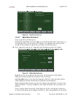
Figure 12 – Auto Adjust “Out of Range”
If this appears then either the signal is too great or (more likely) no signal or a very low signal
is present. Be sure the test/alignment film is playing. Also check that projector’s optical solar
cell is connected and powered. Consult your projector’s manual for more information.
To close this window, press
Dismiss
.
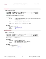
To manually adjust levels, select the button below the left input level bar and use the AP25
front panel adjustment knob to increase or decrease this level until it meets the reference line.
Note: When using a laptop to VNC into the AP25, use the up and down arrows to
mimic the action of the AP25 adjustment knob.
Repeat this step for the Right channel by selecting the button below that level indicator. The
numbers in the buttons indicate the adjustment made to meet the reference level in dB.
F4.4.2.
Film path check
Items needed: Buzz Track test film, oscilloscope, and specific tools required to make
adjustments, such as Allen/Hex Wrenches, small screw driver etc.
Thread up and play the Buzz Track test film. This test film has modulation beyond the
scanned optical areas. If the alignment is off, the error can be seen on the oscilloscope and
also heard on a monitor. The goal is to align the film path so that the slit image is centered on
the soundtrack area of the film. This results in either a null response or equal level on both
tracks. While observing the oscilloscope, make adjustments to the projector’s optics to
achieve the checked example shown below in
. Some adjustments are made by
moving the projector’s film guide laterally, while on others the lens and LED assembly is
moved. Refer to the manufacturer’s procedure regarding the proper adjustment for your model
projector.
Figure 13 – Cell alignment viewed on Oscilloscope using Buzz Track test film


