


P
AGE
38
05725-02-0499 <90-00201>
7.
Remove the 2713 HZ tone, and lower the level to -3 dBm, (10 dB be-
low TLP of +7 dBm) and reinsert the tone for 2 seconds. The loopback
should still function correctly. Remove tone, and reapply it for .7 sec-
onds. The loopback should restore back to normal, and the LED will
turn off.
8.
This completes the 4003C testing, and alignment
S
LOT
10: D
UAL
VF 64
K
B C
HANNEL
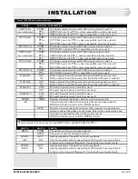
All switch and option settings are factory set. Verify that the
switch settings are per Table A and that the strap settings match
those shown in Fig. 4.
With power on the module, the cables attached to the Sonet
equipment, and a 46105 modules in service on the rest of the
system, the SYNCH LED on the 46105 module will come on
steady. In the repeater mode, both SYNCH LED LEDs will come
on. This is an indication that the framing bits are being detected
by the digital sections of the channels of the module, indicating
synchronization of data transmitted to the 46105. The 46105 is
now able to send data on the system.
NOTE
: The following steps should be used to only verify the level
settings. They should only be required if modules are swapped
out or to test suspected bad modules.
1.
Refer to Fig. 4 and set the bridge terminal switch to terminal. Set the
S2 and S101 to loopback or to on. Reinstall the module and power it
up.
NOTE
: Other parts of the system do not have to be functioning.
2.
Insert a -16 dBm, 600 ohm terminated 1 kHz signal into the DROP
XMT jack of channel 1 on the front panel of the 46105 module.
3.
Insert a 600-ohm bridging dB meter into the blue front panel XMT
LVL test points for channel 1. The reading should be 0 dB. If the level
is not correct, adjust the front panel transmit potentiometer for chan-
nel 1.
4.
Install a terminated 600-ohm dB meter into the DROP RCV jacks for
channel 1. (It can be the same meter as used in step 3 above.) Verify a
level of +7 dBm. If the level is not correct, adjust the front panel re-
ceive potentiometer for RCV 1.
5.
Move the signal generator from channel 1 to the DROP XMT jack for
channel 2.
6.
Insert a 600-ohm bridging dB meter into the blue front panel XMT
LVL test points for channel 2. The reading should be 0 dB. If the level
is not correct, adjust the front panel transmit potentiometer for chan-
nel 2.
CONTINUED
. . .
TURN-UP PROCEDURE


