


P
AGE
12
05725-02-0499 <90-00201>
INSTALLATION
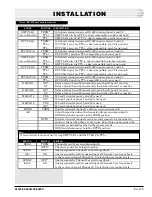
F
IG
. 8 - 46020 MAP V
IEWED
FROM
THE
T
OP
VIEW
ROTATED
90 DEGREES
*
REFER TO NOTE BELOW
1 2 3 4 5 6 7 8
1 2 3 4 5 6 7 8
1 2 3 4 5 6 7 8
1 2 3 4 5 6 7 8
1 2 3 4 5 6 7 8
1 2 3 4 5 6 7 8
SWITCH 7
SWITCH 6
SWITCH 1
SWITCH 2
SWITCH 3
SWITCH 4
UP = OFF
DOWN = ON
1 2 3 4 5 6 7 8
SWITCH 5*
1 2 3 4 5 6 7 8
1 2 3 4 5 6 7 8
1 2 3 4 5 6 7 8
NOTE:
Apply power initially with switch 5 position 7 UP and allow the
MAP to self-configure. Then remove power and place switch 5
position 7 DOWN. This will retain the configuration in
memory.
T
ABLE
C - S
WITCHES
1
THRU
4, 46020-38
SWITCH
SW5
SW6
SW7
POSITION
1
2
3
4
5
6
7
8
1
1
1
1
1
1
*
0
1
1
1
1
1
1
1
1
1
1
1
1
1
1
1
1
* NOTE
: Switch 5 position 7 must be up to configure on initial
power-up. Place down to retain configuration in memory. A 1
indicates that the switch is up (up = OFF). A 0 indicates
that the switch is down (down = ON).
NOTE
: A 1 indicates that the switch is up (up = OFF). A
0 indicates that the switch is down (down = ON).
SWITCH
SW1
POSITION
1
2
3
4
5
6
7
8
0
0
0
0
0
0
0
0
SW2
0
0
0
0
0
1
0
0
SW3
0
0
0
0
0
0
0
0
SW4
0
0
0
0
0
0
0
1
T
ABLE
D - S
WITCH
5-7, 46020-38


