


P
AGE
30
05725-02-0499 <90-00201>
TURN-UP PROCEDURE
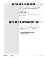
level, verify that the transmit level, at the blue XMT level pin jack
on the front panel of the far end 46105, is 0 dB. If it is not, adjust
the far end transmit potentiometer for 0 dB.
If the transmit level is correct and the RCV level is still not within
+ 1 dB, adjust the local RCV potentiometer until the RCV level is
+7 dBm.
Check the local XMT level to the remote RCV in the same way.
Insert a -16 dBm, 1 kHz tone into the XMT drop jack and check
for a +7 dBm at the far end RCV drop jack. These levels need not
be changed, unless they are not within the + 1 dB tolerance, but
they should be verified on the routine level maintenance schedule.
F
IG
. 16 - T
ONE
L
EVELS
CONTINUED
. . .
Dantel
TELLABS 4003C
46033
E-System
Adapter
PAD
OUT
PAD
IN
202 Tone
Modem
Data XMT
-29 dBm
X
X
X
X
MON
IN
XMIT
OUT
MON
OUT
IN
REC
MON
MON
Loop
-23 dB**
0dB*
*
Transmit & Receive level switches are set at time of turn up to meet facility requirements.
The B18-05725-02 assembly is factory-set for +7 dBm on the RCV and -16 dBm for the XMT.
**
The loopback levels depend on the facilities. For this application, it is set for -23 dB.
0dB*
Data RCV
-6 dBm
Data XMT -29 dBm
TT XMT -16 dBm
Dantel
46105
64kB Channel
Data RCV -6 dBm
TT RCV +7 dBm
XMT DATA
XMT CLK
RCV DATA
RCV CLK


