


P
AGE
34
05725-02-0499 <90-00201>
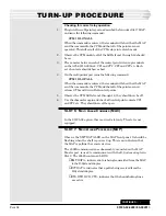
Checking for correct relay operation
1.
Plug into the craft/printer port as described below under Slot 7 MAP,
and issue the following command:
CPM 1 DLON ALL
When the command is entered, the terminal will show that the MAP
sent the command to the CPM and that all of the points are now
operated. This will set all of the CPM relays into a latch mode
2.
Observe the CPM module, all of the LEDs from 1 through 16 should
be on.
3.
Place a meter between each of the control point wire wrap terminals
on the A25-00710-00 block, CP1 and CP1', CP2 and CP2' etc. Each
set of contacts should show a short.
4.
On the craft/printer port issue the following command:
CPM 1 DLOF ALL
When the command is entered, the terminal will show that the MAP
sent the command to the CPM and that all of the points are now
released. This will turn off all control points.
5.
Observe the CPM LEDs from 1 through 16, they should now be off
6.
Use the ohmmeter again and check all control point contacts CP1
and CP1' etc. They should now all be open.
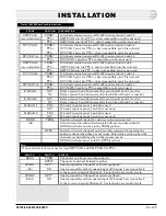
SLOT 6: M
ULTI
A
LARM
C
OMBINER
(MAC)
In the 05725-02 option, this is a wired slot only. The slot is not
equipped.
SLOT 7: M
ULTI
A
LARM
P
ROCESSOR
(MAP)
Observe the XMT DATA LED on the MAP front panel. It should be
flashing when the shelf is powered up. This is an indication that
the MAP is polling the remote devices.
The 49029 communications subassembly, mounted on the MAP
Master port, is used to communicate with the E-System adapter in
Slot 8. The 49029 contains 6 LEDS.
♦
XMT DATA - indicates data is being transmitted from the MAP
to the E-System Adapter.
♦
RCV DATA - indicates that a poll is being received from the
E-System Adapter.
♦
RTS, DTR, DCD, CTS - indicates that the handshaking lines
are active.
CONTINUED
. . .
TURN-UP PROCEDURE


