


05725-02-0499 <90-00201>
P
AGE
25
INSTALLATION
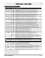
SWITCH
BRDG
LPBK 1
(S2)
LPBK 2
(S101)
SWITCH
TERM
RPTR *
OFF *
ON
OFF *
ON
SWITCH
Channels 1 and 2 operate independently.
Channels 1 and 2 are bridged together.
Analog signals for Channel 1 are not looped back.
Analog signals from the transmit input of Channel 1 are looped back
to the receive output of Channel 1. Use to check or set audio levels.
Analog signals for Channel 2 are not looped back.
Analog signals from the transmit input of Channel 2 are looped back
to the receive output of Channel 2. Use to check or set audio levels.
STRAP
XMT CLK 1
(see note below)
RCV CLK 1
RCV DATA 1
XMT CLK 2
(see note below)
RCV CLK 2
RCV DATA 2
E LEAD 1
E LEAD 2
M LEAD 1
M LEAD 2
MODE
(S1)
POSITION
TERM *
TTL+
TTL
TERM *
TTL+
TTL
TERM *
TTL+
TERM *
TTL+
TTL
TERM *
TTL+
TTL
TERM *
TTL+
NO *
NC
NO *
NC
YES
NO *
YES
NO *
TERM
RPTR *
DESCRIPTION
180-ohm termination across RS-422 inputs at pins 51 and 52
XMT CLK 1 pin 51 is TTL (+ edge) compatible; pin 52 is not used
XMT CLK 1 pin 52 is TTL ( edge) compatible; pin 51 is not used
180-ohm termination across RS-422 inputs at pins 45 and 46
RCV CLK 1 pin 45 is TTL (+ edge) compatible; pin 46 is not used
RCV CLK 1 pin 46 is TTL ( edge) compatible; pin 45 is not used
180-ohm termination across RS-422 inputs at pins 43 and 44
RCV DATA 1 pin 43 is TTL compatible; pin 44 is not used
180-ohm termination across RS-422 inputs at pins 5 and 6
XMT CLK 2 pin 5 is TTL (+ edge) compatible; pin 6 is not used
XMT CLK 2 pin 6 is TTL ( edge) compatible; pin 5 is not used
180-ohm termination across RS-422 inputs at pins 11 and 12
RCV CLK 2 pin 11 is TTL (+ edge) compatible; pin 12 is not used
RCV CLK 2 pin 12 is TTL ( edge) compatible; pin 11 is not used
180-ohm termination across RS-422 inputs at pins 13 and 14
RCV DATA 2 pin 13 is TTL compatible; pin 14 is not used
Relay at pins 39 and 40 is normally open when E Lead 1 is active
Relay at pins 39 and 40 is normally closed when E Lead 1 is inactive
Relay at pins 19 and 20 is normally open when E Lead 2 is active
Relay at pins 19 and 20 is normally closed when E Lead 2 is inactive
M Lead 1 input at pins 41 and 42 is used
M Lead 1 input at pins 41 and 42 is not used
M Lead 2 input at pins 15 and 16 is used
M Lead 2 input at pins 15 and 16 is not used
Digital sections of channel 1 and 2 are not interconnected.
Select this position when the channels will operate independently.
BRDG switch also must be in the TERM position.
Digital sections of channel 1 and 2 are interconnected, bypassing the
analog sections when they are not in use. Select this position when the
channels are bridged together in the repeater mode.
BRDG switch also must be in the RPTR position.
N
OTE
:
If an external clock is not used, strap XMT CLK 1 and XMT CLK 2 to TTL+.
T
ABLE
L - 46105 S
WITCH
AND
S
TRAP
O
PTIONS


