


05725-02-0499 <90-00201>
P
AGE
37
3.
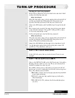
Verify the 49013, 202 modem transmit level is correct by inserting an
unterminated level meter in the pin jacks marked XMT and turning
the test switch on the front of the 49029 on. The level meter should
read -29 dBm. Adjust the XMT level pot (R9) on the 49029 to obtain
the correct reading. Turn the test switch back to normal (not in the
test mode)
Whenever the ESA is polled from TMAS and it recognizes its
address, it will respond to TMAS. When the ESA responds, the
XMT DATA LED on the ESA will flash. Whenever TMAS turns on
its modem and it polls a remote address, the CD LED on the 49013
202-modem sub assembly will turn on. When the ESA XMT DATA
LED flashes, TMAS should see the responses from the ESA. If the
CD LED on the 49029 comes on, but the XMT DATA LED never
comes on, verify that the switch settings for the ESA are set per
Tables E and F. If the switch settings are correct, verify that
TMAS has the correct address for the ESA and it is polling that
address.
S
LOT
9: 4003C L
INE
A
MPLIFIER
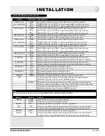
The settings for the 4003C are preset from the factory using the
programmable switch setting on the front of the module. No
changes should be required. Use Tables B, C, and D to verify that
no switches have been changed during shipment.
NOTE:
The following steps should be only be used to verify the level
settings. They should only be required if modules are swapped
or to test suspected bad modules.
1.
Using a Transmission Measuring Set (TMS), insert a terminated
1200 Hz tone at a level of -6 dBm into the RCV IN jacks of the 4003C.
2.
Insert a bridged dB meter at the RCV pin jacks of the 49013 202 mo-
dem on the E-System Adapter. The reading should be -6 dBm. If it is
not 1dB, adjust the programmable switches on the 4003C
until the reading is -6 dBm.
3.
At the RCV IN jacks of the 4003C, insert loopback tone for 2 seconds
(2713 Hz at level at a level of +7 dBm.) This is the Transmission
Level Point (TLP).
NOTE
: 2713 Hz is the factory setting. Final setting for loopback tone is
set per Engineerings instructions.
4.
Observe that the red LED on the 4003C comes on when the loopback
and control circuit are active.
5.
After the red LED comes on, change the test tone in the RCV IN
jacks to 1 kHz at +7 dBm and move the dB meter to the XMT OUT
jacks and terminate it. The level should be -16 dBm, + 1 dB.
6.
Reset the test tone frequency to 2713 HZ for .7 seconds and the
loopback will restore the module and the LED will turn off.
CONTINUED
. . .
TURN-UP PROCEDURE
N
OTE
:
If any level adjust-
ments are required,
make them on the
4003C module in
slot 9 first. Then, if
more adjustments
are needed, adjust
the modem in the
ESA in slot 8. This
will avoid the repeti-
tion of steps.


