


05725-02-0499 <90-00201>
P
AGE
21
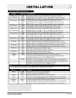
INSTALLATION
ADDRESS
POSITION
1
2
3
4
5
6
7
8
252
253
254
255
1
1
1
1
1
1
0
0
1
1
1
1
1
1
0
1
1
1
1
1
1
1
1
0
1
1
1
1
1
1
1
1
N
OTE
:
A 0 indicates that the
rocker switch is down
adjacent to the position
number (closed = ON).
A 1 indicates that the
rocker switch is up adja-
cent to the position num-
ber (open = OFF).
NOR
RCV
S2
1
13
P5
1
4
P4
MAS SLA
XMT
RCV
MAS SLA
OUT
IN
IN
U2
U1
-00
-01
*
*
Reset, Factory use only.
T
ABLE
G (
CONTINUED
) - 46033 E-S
YSTEM
A
DAPTER
S2 S
WITCH
S
ETTINGS
49013 202 Tone Modem Subassembly
Refer to Fig. 11 and Table H for switch and strap settings.
F
IG
. 11 - 49013 202 T
ONE
M
ODEM
S
WITCH
AND
S
TRAP
L
OCATIONS
T
ABLE
H - 49013 202 T
ONE
M
ODEM
S
WITCH
AND
S
TRAP
O
PTIONS
OPTION
Transmitter Master/Slave
Receiver Master/Slave
RCV Pad In (input level 0 to -20 dB)
XMT Pad In (output level adjustable
between -20 and -40 dBm)
S2
INSTALL STRAP
Remove or store in inoperative position (see Fig. 11)
Remove or store in inoperative position (see Fig. 11)
Jumpers placed parallel to connector P5
Jumpers placed parallel to connector P5
NOR (Toward connector P5)


