


P
AGE
10
05725-02-0499 <90-00201>
T
ABLE
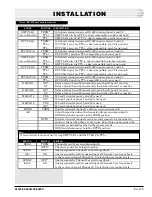
A - 46009 MAT S
WITCH
AND
S
TRAP
O
PTIONS
INSTALLATION
SWITCH
SW5
Slot 1 **
Slot 2 ***
SW4
SW3
SW6
SW301
POSITION
1
2
3
4
5
6
7
8
0
1
1
0
1
1
1
1
0
1
1
0
1
1
0
1
1
1
0
1
0
0
0
1
0
1
1
1
1
1
1
1
1
1
1
1
-
-
-
-
0
1
-
-
-
-
-
-
NOTE
: A 1 indicates that the switch is up (up = OFF). A 0
indicates that the switch is down (down = ON).
**
DCM addresses 17/18 (display 5, bits 1-32)
***
DCM addresses 19/20 (display 5, bits 33-63)
NOTE:
The MATs in slots 1 and 2 are not interchangeable without changing
the address on switch 5 first.
46028 Control Point Module (CPM)
Refer to Fig. 6 and Table B.
F
IG
. 6 - 46028 CPM S
WITCH
AND
S
TRAP
L
OCATIONS
1
13
1
4
J5
J4
SUBASSEMBLY
MOUNTING
AREA
OFF
1
8
OFF
1
8
S1
S2
UP=OFF
DOWN=ON
A
NORM
REV
S3
B
Bottom Edge View
SWITCH 1
SWITCH 2
UP = OFF
DOWN = ON
1 2 3 4 5 6 7 8
1 2 3 4 5 6 7 8


