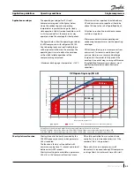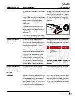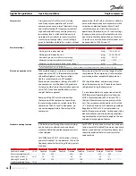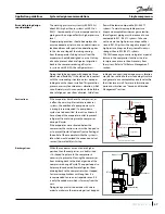
Application guidelines
45
FRCC.PC.023.A7.22
Single compressors
Operating conditions
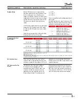
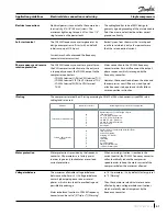
Insufficient oil level can be the result of oil
depositing itself in pipes and heat exchangers.
The oil deposit can be returned to the crankcase,
by increasing velocity for short periods, at regular
time intervals or when velocity is too low to
ensure adequate oil returns.
With oil return management these two oil return
mechanisms can be programmed in the CDS303.
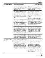
With oil return management function enabled,
the CDS303 performs oil return by boosting the
compressor speed to 4200 rpm (70 rps) for a
selectable duration as programmed in parameter
28.13. The boosts are performed at fixed time
intervals (as programmed in parameter 28.12)
or if the compressor speed has been less than
3000 rpm (50 rps) for too long (as programmed in
28.11) whichever occurs first. Thus the maximum
time between two consecutive oil return boosts
is programmed in 28.12.
Considering oil return risk, split system with
more than 10m piping length need mandatory
application approval by Danfoss application
specialists.
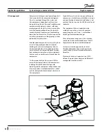
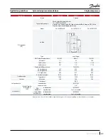
Use the accessory “oil level switch” with the
appropriate compressor housing having the
fitting pre assembled and refer to "VZH hybrid
manifolding" section at the end of this document.
Oil return management
function (single compressor)
Oil return management in
hybrid manifolding
The discharge gas temperature must not exceed
275°F.
A discharge gas temperature protection device
must be installed on all heat pumps. In reversible
air-to-air and air-to-water heat pumps the
discharge temperature must be monitored
during development test by the equipment
manufacturer.
The compressor must not be allowed to cycle
on the discharge gas thermostat. Continuous
operations beyond the compressor’s operating
range will cause serious damage to the
compressor!
A DGT accessory is available from Danfoss: refer
to accessories pages at the end of this document.
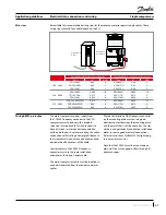
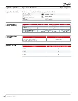
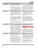
The discharge gas thermostat accessory kit (code
no.7750009) includes all components required
for installation, as shown below. The thermostat
must be attached to the discharge line within
5.91 inch from the compressor discharge port
and must be thermally insulated and tightly fixed
on the pipe.
Discharge line
Insulation
Bracket
Thermostat
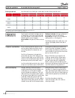
ID
Name
Factory
Setup
"long pipe
(25-30m)"
Unit
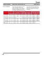
2810 Oil Return
Management
On
On
2811 Low Speed Running
Time
60
30
min
2812 Fixed Boost Interval
24
6
h
2813 Boost Duration
30
60
s
High and low pressure
protection
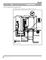
High pressure
According to EN378-2, a high-pressure (HP) safety
switch is required to shut down the compressor.
The high-pressure switch can be set to lower
values depending on the application and
ambient conditions. The HP switch must either be
placed in a lockout circuit or consist of a manual
reset device to prevent cycling around the high-
pressure limit. If a discharge valve is used, the HP
switch must be connected to the service valve
gauge port, which must not be isolated. The HP
switch must be connected to the CDS303 input
37 or an external contactor placed between the
drive and the compressor.

