8
MG.30.A7.02 - VLT
®
is a registered Danfoss trademark
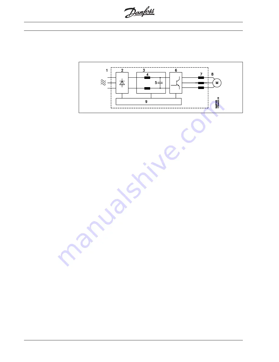
A frequency converter rectifies the a.c.
voltage to
D.C.
voltage and then converts
this
D.C.
voltage to A.C. voltage with
variable amplitude and frequency.
The variable voltage and frequency
supplying the motor make possible infinite
speed control of standard three-phase
asynchronous motors.
Control principle
1.
Mains supply
3 x 200 / 220 / 230 V A.C., 50/60 Hz
3 x 380 / 400 / 415 V A.C., 50/60 Hz
3 x 440 / 460 / 500 V A.C., 50/60 Hz
2.
Rectifier
Three-phase rectifier bridge rectifies
A.C. to D.C..
3.
Intermediate circuit
D.C. voltage =
√
2 x supply voltage.
4.
Coils in the intermediate circuit
Smooth
the D.C.
voltage and limit
the mains supply harmonics.
5.
Capacitors in the intermediate circuit
Smooth- the
D.C.
voltage.
6.
Inverter
Converts
D.C.
voltage to variable
A.C.
voltage and variable frequency.
7.
Motor coils
Advantages of motor coils:
•
You can use longer motor cables
•
100% short-circuit and earth-fault
protected
•
Unlimited switching at the output of
the frequency converter.
•
Reduces du/dt.
8.
Output
Variable
A.C.
voltage, 10 -100% of
the supply voltage.
Variable frequency: 0.5-120 / 0.5-500 Hz.
9.
Control card
This section controls and monitors the
power and inverter section, which
generates the pulse pattern by means
of which the
D.C.
voltage is converted
to variable
A.C.
voltage and variable
frequency.
Introduction


