background image

Micromon

Micromon

RS.8A.Y3.02 


©

Danfoss

01-2003

13

When you have finished or to abandon the operation, press ‘

’ once to return to

the Setup Menu and again to return to the Main Menu.

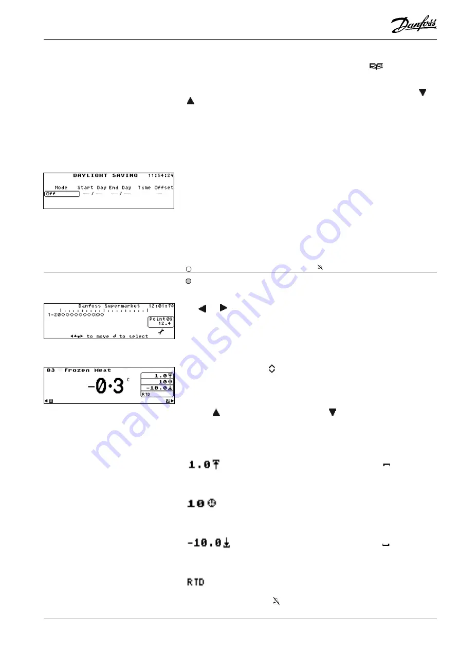
This option is to set the automatic clock change for winter/summer. Use the ‘

’ or

’ keys to scroll through the following options:

Mode -

Off

-

Daylight saving switched off.

Auto-US

-

American daylight saving time settings.

Auto-EU

-

European daylight saving time settings.

Manual

-

Times and offset can be manually set.

Start Day

-

Date for when time changes for summertime.

End Day

-

Date for when time changes back for wintertime.

Time

-

The hour at which the change will take place.

Offset

-

The amount in hours the clock will change.

The Point Overview screen is the default screen and views the status of all the
points at the same time, showing each activated point as one of the following
icons, depending on the point condition. This screen can also be selected from the
Point Overview option from the Main Menu.

 - active point in normal condition

 - an inhibited point

 - active point in an alarm condition

To select a point, the cursor box can be positioned around a point symbol by using
the ‘

 ‘ or ‘

 ‘ keys.  As each point is selected the point number and its current

status/temperature is displayed in the window on the right hand side of the screen.

To display more details of a particular point, position the cursor box around the
point required and press ‘

↵↵

↵↵

’.  The Point Detail screen will be displayed.

Note: If a point has a local offset applied to it, this will be indicated by the

presence of the offset icon 

 at the left of the Point Readout window.

To continuously view the status of a single point, either select the Point Detail
option from the Main Menu or select a point on the Point Overview and press ‘

↵↵

↵↵

’.

The Point Detail screen is displayed.
Use the ‘

’ key to select the next point or the ‘

’ key to select the previous point.

The point number is displayed in the upper left-hand corner of the screen and the
current status is displayed in large text in the centre of the screen.
The text and symbols displayed in the window on the right hand side of the screen
are as follows:

Indicates the upper alarm limit setting.  When the  

 of the

symbol is scrolling, it indicates that the upper alarm limit has
been exceeded.

Indicates the alarm delay in minutes.  When the hand of the clock

rotates, it indicates that the point is in the alarm

condition and

the delay has not yet expired.

Indicates the lower alarm limit setting.  When the 

part of the

symbol is scrolling, it indicates that the lower alarm limit has
been exceeded.

Indicates the input point type.

The area adjacent the 'Input Point Type' also displays 'inhibit' and 'pulldown' icons.

- an inhibited point.

Operation via the Key Pad

Point Overview

Point Detail

Dial

Answer

Daylight Saving

Summary of Contents for Micromon

Page 1: ...Monitoring and Alarm System Micromon Manual Refrigeration and Air Conditioning Controls R E F R I G E R A T I O N A N D A I R C O N D I T I O N I N G...

Page 2: ...PointType 10 Passcode Setup 10 Log Graph Setup 10 Modem Dialout Setup 11 Dialout 11 CallType 11 Number 12 Pager Info 12 Send 12 Modem Configuration 12 Baud Rate 12 Point Detail 13 Point Overview 13 O...

Page 3: ...inted on a regular basis The data is accessible both on and off site via the external modem connection and alarm calls can also be gener ated if required The Micromon has been designed in such a way t...

Page 4: ...nsors The Micromon provides audio and visual alarms whenever an input exceeds its pre set alarm levels The system can be pre set to dial out using a digital dialler or via a modem whenever an alarm oc...

Page 5: ...ey will force the highlight to the bottom of the menu In addition when a character entry field has been selected this key is used to increment the displayed value in the entry field SecondaryFunctions...

Page 6: ...ursor to the Graph screen and selects points on the Overview screen Backspace in edit fields Adjusts Screen Contrast Accented special characters editing mode or Sort and display alarms by point when i...

Page 7: ...nt up or down to the required number This screen is used select the application of those points that have just been selected in the previous screen Use the and keys to move the cursor to the required...

Page 8: ...y to move the active field box around the temperature units field then use the or key to toggle betweenFahrenheitandCentigrade The date format of the Micromon unit can be set to either DD MM or MM DD...

Page 9: ...selected points on a timed or demand basis via the print menu Timed means the Micromon is programmed to automatically print a log at preselected intervals A log printout can also be initiated via the...

Page 10: ...he Passcode Setup option Use the to highlight the passcode to be modified Type in the passcode using the or keys to scroll through the character list and the or key to move the cursor left or right re...

Page 11: ...this field to specify the type of device which is connected to the specified telephone number The options are as follows NO DIAL Indicates the Micromon will not dialout GSM SMS Indicates that a RS232...

Page 12: ...s S Sends the Store Name A Sends the Last Alarm Message C Sends a count of alarms and muted alarms in the format2 4 R Sends the Carriage Return CR character L Sends the Line Feed LF character Sends th...

Page 13: ...the screen To display more details of a particular point position the cursor box around the point required and press The Point Detail screen will be displayed Note If a point has a local offset appli...

Page 14: ...sses etc These offsets are point specific and may only be defined from the Micromon keypad although their value is readable when accessing the unit remotely Under normal circumstances these offsets if...

Page 15: ...te Options which have a symbol alongside them are password protected Use this option to display the default Point Overview screen as previously described To display the alarm history select the Alarm...

Page 16: ...ired value and the key to move through each field The Printing In Operation screen is then displayed and the data is sent to the printer Each alarm is given a number from 1 to 999 restarting at 1 afte...

Page 17: ...e n h c a e n o e v i t c A d e s s e r p s i y e k E T U M m r a l A p e R 2 Y A L E R a r o f n o i t c e n n o c d e y a l e R t i n u m r a l A t a e p e R l l i t s e r a s m r a l a e l i h w e...

Page 18: ...viced only by qualified service personnel and should ensure that replacement parts match the original safety characteristics CAUTION This unit is fitted with rechargeable batteries use only manufactur...

Page 19: ...M can be used to control the modem power The Relay is rated at 24V 1A max so the low voltage power after the mains transformer must be switched Mains voltage MUST NOT be connected to this relay Modem...

Page 20: ...that such alternations can be made without subsequential changes being necessary in specifications already agreed All trademarks in this material are property of the respecitve companies Danfoss and...

Reviews: