background image

10

Manual

RS

.8A.Y3.02  


©

Danfoss

01-2003

 Micromon

On

Set this option to ON if you require a graph for this

point to be included in all graph printouts.

Repeatedly press ‘

↵↵

↵↵

 to scroll through the fields until the Graph field is highlighted.

Use the '

' or '

' keys to set the required graph action.

A point can be setup for 4-20mA application such as pressure, transducers, temp,
flow, humidity, level etc. This can only be used on a point that had been previously
set to 'Off'.
Select a 'Off' point by scrolling through the point numbers, then select the type
field and set to '420'.

The default values for the 4-20mA are 0 to 100% (0 = 4mA and 100 = 20mA). Zero
and full scale can be modified via the second Point Detail screen.
With the 'Type' field highlighted, press the ‘

’ key to display the second Point

Detail screen. The 4 and 20 values can be set. The value for the upper and lower
limits can therefore represent % (RH), PPM, bar, psi etc, depending on the
medium being measured. A numerical value for 4mA (lower limit) and 20mA
(higher limit) is entered and the Micromon automatically scales the input for a
figure proportional to the measurement.

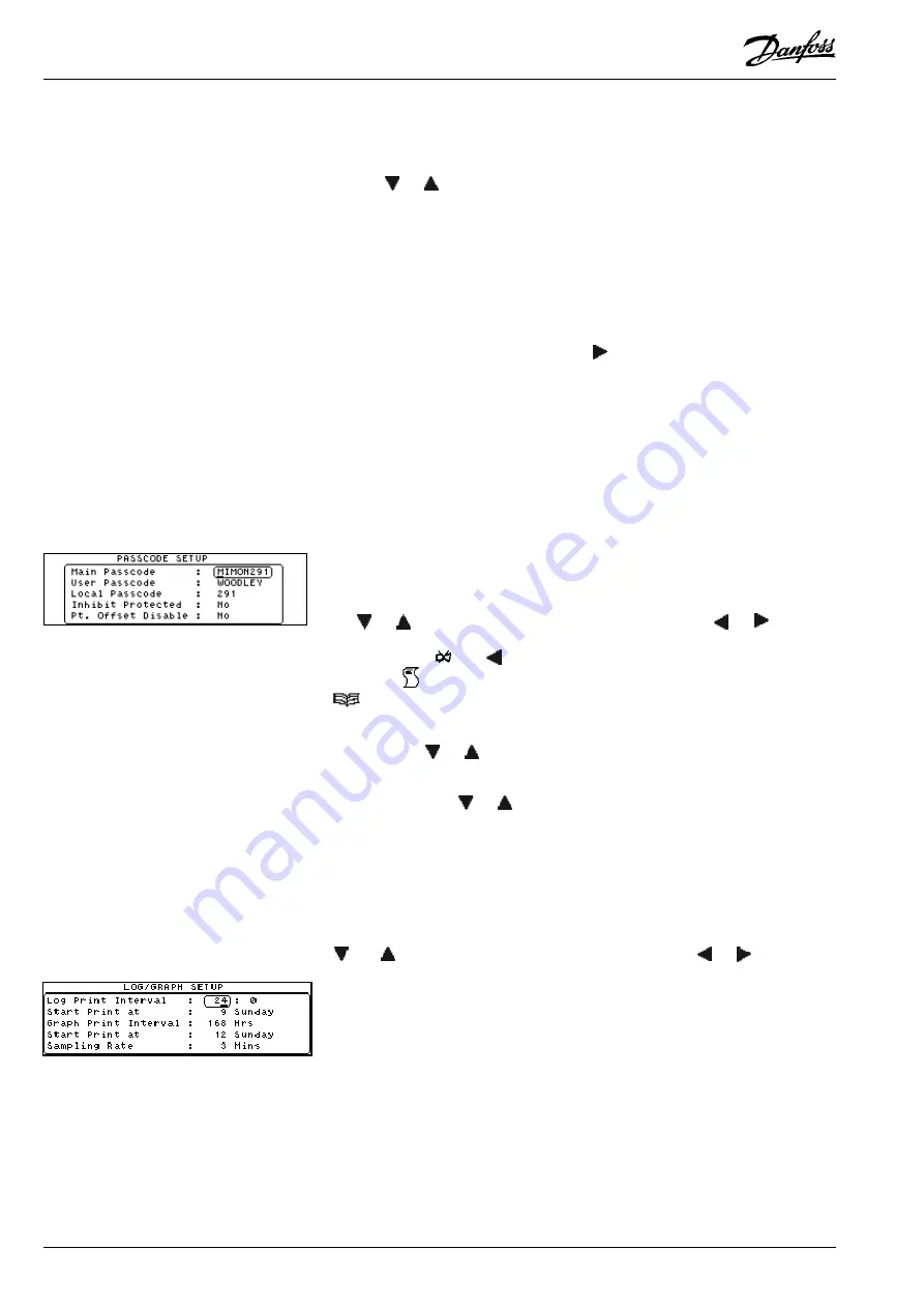
This option allows you to change the three different levels of passcodes – Main,
User and Local, also the Inhibit Protection and Point Offset protection can be
activated.  The Main and Local Passcode provides access to all the setup
screens.  The User Passcode only provides access to the Time/Date setup.
The Micromon default setting are as displayed in the screen shown on the left.

From the Extended Menu, select the Passcode Setup option.

Use the ‘

↵↵

↵↵

 to highlight the passcode to be modified.  Type in the passcode using

the ‘

’ or ‘

’ keys to scroll through the character list and the ‘

’ or ‘

’ key to

move the cursor left or right respectively. N.B. Local passcode is numeric only.
You can use the ‘

‘ and ‘

’ keys together to delete the character before the

cursor and ‘

‘ to change case.  When the passcode has been set, press ‘

↵↵

↵↵

’ then

’ to return to the Setup Menu.

To set the Inhibit Protection, use the ‘

↵↵

↵↵

 key to highlight the 'Inhibit Protected' field,

then using the ‘

’ or ‘

’ keys to select either 'Yes' or 'No'.

To set the Point Offset Disable, use the ‘

↵↵

↵↵

 key to highlight the 'Pt Offset Disable'

field, then using the ‘

’ or ‘

’ keys to select either 'Yes' or 'No'.

The log print and graph print settings only apply if a printer is connected directly to
the Micromon. If no printer is used, only select the Sampling Rate if needed.
To set the print frequencies, select the Log/Chart Frequency option from the Setup
Menu.

Use the ‘

↵↵

↵↵

 to highlight the field to be modified.  Type in the time required using the

’and ‘

’ keys to scroll through the character list and the ‘

’ or ‘

’ key to move

the cursor left or right respectively.

Set the values as follows:

Log Print Interval

Set this value to determine the interval (i.e. frequency)
between log prints (hours : minutes).

Start Print at

Enter the time and day on which you require the first
printing of the automatic log readings to start. (Only points
that have been set as Timed or ON will be included).

Graph Print Interval Set this value to determine the interval (i.e. frequency)

between graph prints.

Start Print at

Enter the time and day on which you require the first
automatic graph to be printed. (Only points that have been

Log/Graph Setup

Passcode Setup

4-20mA Point Type

Summary of Contents for Micromon

Page 1: ...Monitoring and Alarm System Micromon Manual Refrigeration and Air Conditioning Controls R E F R I G E R A T I O N A N D A I R C O N D I T I O N I N G...

Page 2: ...PointType 10 Passcode Setup 10 Log Graph Setup 10 Modem Dialout Setup 11 Dialout 11 CallType 11 Number 12 Pager Info 12 Send 12 Modem Configuration 12 Baud Rate 12 Point Detail 13 Point Overview 13 O...

Page 3: ...inted on a regular basis The data is accessible both on and off site via the external modem connection and alarm calls can also be gener ated if required The Micromon has been designed in such a way t...

Page 4: ...nsors The Micromon provides audio and visual alarms whenever an input exceeds its pre set alarm levels The system can be pre set to dial out using a digital dialler or via a modem whenever an alarm oc...

Page 5: ...ey will force the highlight to the bottom of the menu In addition when a character entry field has been selected this key is used to increment the displayed value in the entry field SecondaryFunctions...

Page 6: ...ursor to the Graph screen and selects points on the Overview screen Backspace in edit fields Adjusts Screen Contrast Accented special characters editing mode or Sort and display alarms by point when i...

Page 7: ...nt up or down to the required number This screen is used select the application of those points that have just been selected in the previous screen Use the and keys to move the cursor to the required...

Page 8: ...y to move the active field box around the temperature units field then use the or key to toggle betweenFahrenheitandCentigrade The date format of the Micromon unit can be set to either DD MM or MM DD...

Page 9: ...selected points on a timed or demand basis via the print menu Timed means the Micromon is programmed to automatically print a log at preselected intervals A log printout can also be initiated via the...

Page 10: ...he Passcode Setup option Use the to highlight the passcode to be modified Type in the passcode using the or keys to scroll through the character list and the or key to move the cursor left or right re...

Page 11: ...this field to specify the type of device which is connected to the specified telephone number The options are as follows NO DIAL Indicates the Micromon will not dialout GSM SMS Indicates that a RS232...

Page 12: ...s S Sends the Store Name A Sends the Last Alarm Message C Sends a count of alarms and muted alarms in the format2 4 R Sends the Carriage Return CR character L Sends the Line Feed LF character Sends th...

Page 13: ...the screen To display more details of a particular point position the cursor box around the point required and press The Point Detail screen will be displayed Note If a point has a local offset appli...

Page 14: ...sses etc These offsets are point specific and may only be defined from the Micromon keypad although their value is readable when accessing the unit remotely Under normal circumstances these offsets if...

Page 15: ...te Options which have a symbol alongside them are password protected Use this option to display the default Point Overview screen as previously described To display the alarm history select the Alarm...

Page 16: ...ired value and the key to move through each field The Printing In Operation screen is then displayed and the data is sent to the printer Each alarm is given a number from 1 to 999 restarting at 1 afte...

Page 17: ...e n h c a e n o e v i t c A d e s s e r p s i y e k E T U M m r a l A p e R 2 Y A L E R a r o f n o i t c e n n o c d e y a l e R t i n u m r a l A t a e p e R l l i t s e r a s m r a l a e l i h w e...

Page 18: ...viced only by qualified service personnel and should ensure that replacement parts match the original safety characteristics CAUTION This unit is fitted with rechargeable batteries use only manufactur...

Page 19: ...M can be used to control the modem power The Relay is rated at 24V 1A max so the low voltage power after the mains transformer must be switched Mains voltage MUST NOT be connected to this relay Modem...

Page 20: ...that such alternations can be made without subsequential changes being necessary in specifications already agreed All trademarks in this material are property of the respecitve companies Danfoss and...

Reviews: