background image

12

Manual

RS

.8A.Y3.02  


©

Danfoss

01-2003

 Micromon

PAGER7S

Indicates that a TAP 7 bit protocol pager is connected which can

display a message. The message sent is defined on the Pager

Info line (7 bit, Even Parity, 1 Stop Bit).
PAGER7M

Identical to PAGER7S but sends message up to 4 times.

PAGER8S

Indicates that a TAP 8 bit protocol pager is connected which can

display a message. The message

sent is defined on the Pager

Info line (8 bit, No Parity, 1 Stop Bit).

PAGER8M

Identical to PAGER8S but sends message multiple times.

Enter the appropriate telephone numbers for each of the devices used.  If a
comma ‘,’ is inserted before the number, a delay of between 2 and 4 seconds will
be inserted between the modem picking up the line and dialling.  If a ‘w’ is inserted
before the number, the modem will wait for the secondary tone before dialling.

For a message to be sent to a pager, two items of information must be supplied in
addition to the TAP Pager server telephone number.

1.

The pager I/D, this is normally marked on the pager.

2.

The text message to be sent to the pager.

Text codes are available that add other information into the message. These
codes are as follows:

\S

Sends the Store Name.

\A

Sends the Last Alarm Message

\C

Sends a count of alarms and muted alarms in the
format 2/4.

\R

Sends the Carriage Return (CR) character.

\L

Sends the Line Feed (LF) character.

\\

Sends the \ character.

//

Sends the / character.

\N

Sends output name.

A typical text string will take the form:

123456\R

Alarm at \S = \A\R

This page info string would cause pager '123456' to receive a message in the form

"Alarm at Danfoss Superstore = 24 Fresh Fish

6.4 Hi>6.0"

The pager info field is limited to a maximum of 30 characters

Use the ‘

’ or ‘

’ keys to select the option of the modem dialling out 'Alarms

Only' or 'Alarms and Cleared Alarms'.

Finally, press ‘

’ to return to the Setup Menu.

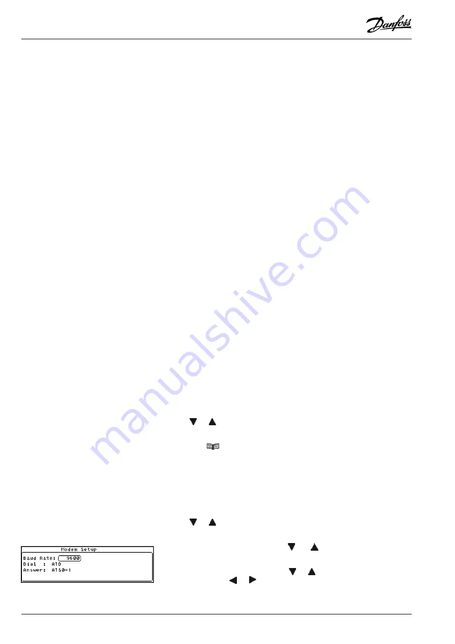
When connected to a modem, use this option to configure the modem settings.
From the Setup Menu, select the Modem Configuration option.

Use the ‘

’ or ‘

’ keys to scroll through the valid baud rates to the required value

and press ‘

↵↵

↵↵

 to move onto the next field.

Enter the dial code you require.  Use the ‘

’and ‘

’ keys to scroll through the

character list and the ‘‘and ‘‘ keys to move the cursor left or right respectively.

Enter the answer code you require.  Use ‘

’ or ‘

’ keys to scroll through the

character list and the ‘

‘ or ‘

‘ key to move the cursor left or right respectively.

Note:  Refer to your modem handbook for details of the valid modem commands
and answer codes.

Pager Info

Modem Configuration

Baud Rate

Send

Number

Summary of Contents for Micromon

Page 1: ...Monitoring and Alarm System Micromon Manual Refrigeration and Air Conditioning Controls R E F R I G E R A T I O N A N D A I R C O N D I T I O N I N G...

Page 2: ...PointType 10 Passcode Setup 10 Log Graph Setup 10 Modem Dialout Setup 11 Dialout 11 CallType 11 Number 12 Pager Info 12 Send 12 Modem Configuration 12 Baud Rate 12 Point Detail 13 Point Overview 13 O...

Page 3: ...inted on a regular basis The data is accessible both on and off site via the external modem connection and alarm calls can also be gener ated if required The Micromon has been designed in such a way t...

Page 4: ...nsors The Micromon provides audio and visual alarms whenever an input exceeds its pre set alarm levels The system can be pre set to dial out using a digital dialler or via a modem whenever an alarm oc...

Page 5: ...ey will force the highlight to the bottom of the menu In addition when a character entry field has been selected this key is used to increment the displayed value in the entry field SecondaryFunctions...

Page 6: ...ursor to the Graph screen and selects points on the Overview screen Backspace in edit fields Adjusts Screen Contrast Accented special characters editing mode or Sort and display alarms by point when i...

Page 7: ...nt up or down to the required number This screen is used select the application of those points that have just been selected in the previous screen Use the and keys to move the cursor to the required...

Page 8: ...y to move the active field box around the temperature units field then use the or key to toggle betweenFahrenheitandCentigrade The date format of the Micromon unit can be set to either DD MM or MM DD...

Page 9: ...selected points on a timed or demand basis via the print menu Timed means the Micromon is programmed to automatically print a log at preselected intervals A log printout can also be initiated via the...

Page 10: ...he Passcode Setup option Use the to highlight the passcode to be modified Type in the passcode using the or keys to scroll through the character list and the or key to move the cursor left or right re...

Page 11: ...this field to specify the type of device which is connected to the specified telephone number The options are as follows NO DIAL Indicates the Micromon will not dialout GSM SMS Indicates that a RS232...

Page 12: ...s S Sends the Store Name A Sends the Last Alarm Message C Sends a count of alarms and muted alarms in the format2 4 R Sends the Carriage Return CR character L Sends the Line Feed LF character Sends th...

Page 13: ...the screen To display more details of a particular point position the cursor box around the point required and press The Point Detail screen will be displayed Note If a point has a local offset appli...

Page 14: ...sses etc These offsets are point specific and may only be defined from the Micromon keypad although their value is readable when accessing the unit remotely Under normal circumstances these offsets if...

Page 15: ...te Options which have a symbol alongside them are password protected Use this option to display the default Point Overview screen as previously described To display the alarm history select the Alarm...

Page 16: ...ired value and the key to move through each field The Printing In Operation screen is then displayed and the data is sent to the printer Each alarm is given a number from 1 to 999 restarting at 1 afte...

Page 17: ...e n h c a e n o e v i t c A d e s s e r p s i y e k E T U M m r a l A p e R 2 Y A L E R a r o f n o i t c e n n o c d e y a l e R t i n u m r a l A t a e p e R l l i t s e r a s m r a l a e l i h w e...

Page 18: ...viced only by qualified service personnel and should ensure that replacement parts match the original safety characteristics CAUTION This unit is fitted with rechargeable batteries use only manufactur...

Page 19: ...M can be used to control the modem power The Relay is rated at 24V 1A max so the low voltage power after the mains transformer must be switched Mains voltage MUST NOT be connected to this relay Modem...

Page 20: ...that such alternations can be made without subsequential changes being necessary in specifications already agreed All trademarks in this material are property of the respecitve companies Danfoss and...

Reviews: