PC2-CamLink User's Manual
Part I: PC2-CamLink Board
•
33
Shaft Encoder
Web inspection systems with variable web speeds typically provide one or two synchronization signals
from a web mounted encoder to coordinate trigger signals. The trigger signals are used by the
acquisition linescan camera. The PC2-CamLink supports single or dual shaft encoder signals. Dual
encoder signals are typically 90° out of phase relative to each other and provide greater web motion
resolution. When using only one shaft encoder input phase, phase A for example, the phase B inputs
must be terminated by connecting the + input to a minimum voltage of 100mV positive relative to the
input.
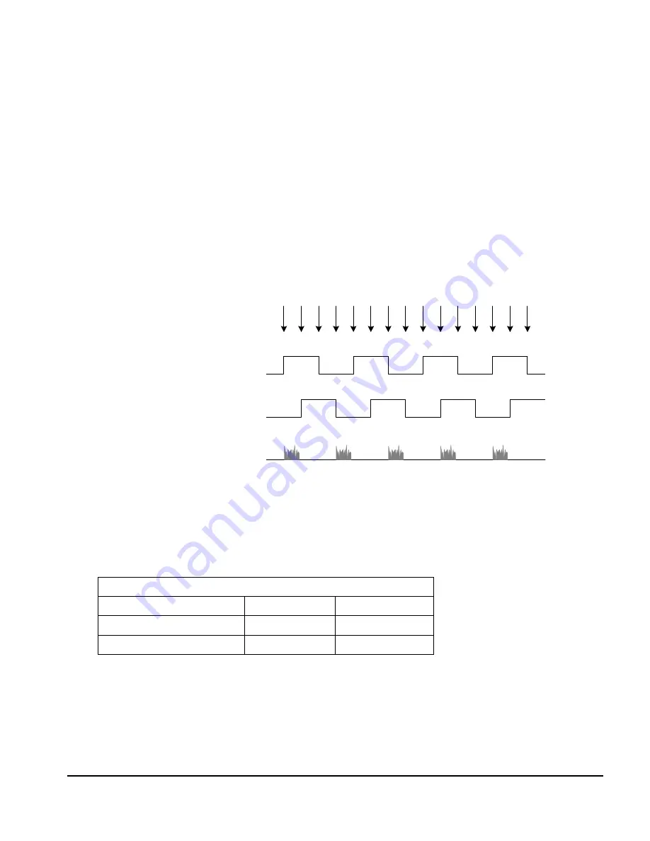
When enabled, the camera is triggered and acquires one scan line for each shaft encoder pulse edge.
To optimize the web application, a second parameter defines the number of triggers to skip between
valid acquisition triggers. The figure below depicts a system where a valid camera trigger is any pulse
edge from either shaft encoder signal. After a trigger, the two following triggers are ignored (as
defined by a trigger drop count parameter).
K
D
D
K
D
D
K
D
D
K
D
D
K
D
D
Shaft Encoder phase A
Shaft Encoder phase B
K = Keep
D = Drop or Skip
Note: in this example, number of triggers to drop = 2
Line acquired
Figure 7: Shaft Encoder
Two LVDS pins on the DB-15 connector provide access to phase A and B of the shaft encoder. These
LVDS pins are debounced to remove any glitch. LVDS shaft encoder inputs are typically implemented
using National Semiconductor DS90LV028A LVDS line receiver or a compatible device.
Pinout:
Positive line
Negative line
Shaft Encoder Phase A
DB-15, pin 6
DB-15, pin 13
Shaft Encoder Phase B
DB-15, pin 7
DB-15, pin 14
A TTL shaft encoder signal can be directly connected to the PC2-CamLink LVDS/RS422 (+) input,
but the low side (-) input of the pair must be biased with a DC voltage to ensure reliable operation.
Suggestions on how to generate the DC bias voltage are given below. The actual physical wiring is left
as an additional detail when interfacing a shaft encoder to the PC2-CamLink and then to the imaging
system itself.
Summary of Contents for PC2-CamLink
Page 7: ...PC2 CamLink User s Manual Part I PC2 CamLink Board 3 Part I PC2 CamLink Board ...
Page 8: ...4 Part I PC2 CamLink Board PC2 CamLink User s Manual ...
Page 10: ...6 Part I PC2 CamLink Board PC2 CamLink User s Manual EC FCC Certificate of Conformity ...
Page 83: ...PC2 CamLink User s Manual Part I PC2 CamLink Board 79 ...
Page 84: ......
Page 85: ...PC2 CamLink User s Manual Part II Sapera LT 81 Part II Sapera LT ...
Page 86: ...82 Part II Sapera LT PC2 CamLink User s Manual ...
Page 105: ...PC2 CamLink User s Manual Part III IFC 101 Part III IFC ...
Page 106: ...102 Part III IFC PC2 CamLink User s Manual ...
Page 116: ...112 Part III IFC PC2 CamLink User s Manual ...
Page 118: ...114 Part IV Troubleshooting and Support PC2 CamLink User s Manual ...
Page 130: ...126 Glossary of Terms PC2 CamLink User s Manual ...


