

54
MAN# 650814
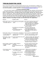
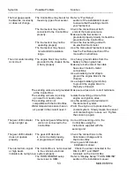
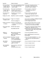
Symptom
Possible Problem
Solution
-----------------------------------------------------------------------------------------------------------------------------------
The check engine
The Control Box ENGINE terminal This feature is designed to work
indicator does not
is not connected to an EFI
with engine control systems that
operate properly.
control module.
provide an active low signal.
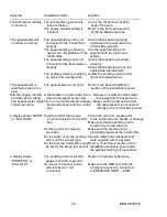
The check engine
The Engine Control Module
Connect a light or similar load
indicator stays on
(ECM) needs to see the
to the ECM along with the
all of the time.
load of a light connected to it.
Control Box.
T
he clock doesn’t
Constant power terminal is
Ensure constant power terminal
keep time.
losing power.
has 12v even when key is off.
Display is too dark.
Brightness needs to be adjusted.
See manual for brightness adjusting
instructions.
Back up camera not Trigger not configured
Check setting in SETUP-CAMERA-TRIGGER
displaying video
Check wiring to Control Box
Camera not plugged in
Confirm trigger signal is valid
Display is blue when Camera is not powered on
Check power at camera when in reverse
in reverse
or video is not at Instrument
Make sure RCA connector is plugged in
CLUSTER
to the rear of the Instrument Cluster
Using GPS, speed
No GPS data received
GPS receiver may still be trying to acquire
reads 0
satellite, this may take 5-15 min,
No satellites detected
Metal structure may be blocking signals, so
move vehicle outside, away from possible
interference objects
‘NO DATA’
BIM providing information
Check wiring and BIM connection
message
is not connected
BIM is non setup properly
Refer to BIM manual for correct setup
Faulty BIM
Replace BIM
‘NOT SUPPORTED’ READING or GAUGE
Change the ARRANGEMENT to one that
message
selection not allowed
will support the desired READING or
for the ARRANGEMENT
GAUGE
‘XXX OPEN’
No connection to selected
Check connection for loose or no contact
message
sensor at control box
Broken or cut wire
Fix wire or replace sensor
‘XXX SHORTED’
Sensor wiring to control box
Check connection for short
message
terminals
Pinched wire from sensor
Fix wire or replace sensor


