41
MAN# 650814
CYLINDER
will allow the RPM signal to be calibrated from 1
– 16 or BIM can be selected if a
Dakota Digital BIM-01-X is connected. If the engine is running the tachometer needle will
update as the settings are changed.
TYPE
will select between two different tach-input types. A low voltage tach signal (5V LOW)
or a high voltage tach signal (12V HIGH). A low voltage signal is usually one that would be
obtained from the ECM. Low voltage may also be considered a 0-5V square wave. If you
are getting the tach signal from the ignition coil or points, set this for the high voltage signal
“12V HIGH”. To obtain a tach signal from a traditional ignition coil, connect a signal wire to
the negative side of the coil.
BACK
exits the INPUT menu and returns to the TACH menu.
NOTE: When selecting the cylinder count, be aware of tach signals coming from ECMs,
some V-8 engine computers may actually output a 4 cylinder tach signal. This would
require the CYLINDER selection to be set
for “4” not “8” as you might expect.
UPDATE RATE (Display update setup)
The display update rate can be adjusted so the reading on the digital tachometer doe
sn’t
change so quickly. This is a personal preference and is just used to stabilize the reading by
averaging. The value can be changed from SLOW, MID, or FAST.
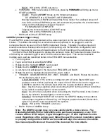
SHIFT LIGHT (RPM warning setup)
This RPM set point is used for the turn-on point for the TACH output terminal on the Control
Box as well as the trigger for the configured GRAFIX Warning Systems. When the RPM
reading is above this setting, the TACH output terminal on the Control Box will activate,
providing a ground signal. This low level signal can be used to turn on a shift light or other
RPM based devices. The value is adjustable from 2,000 RPM
– 15,000 RPM in 250 RPM
increments. Other configured GRAFIX warning mechanisms will also be triggered.
BACK (exit TACH setup sub-menu)
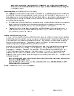
VOLT (Voltmeter warning setup)
The volt setup allows the user to set warnings point that will trigger the configured GRAFIX
Warning Systems if violated. Whenever the voltage reading is above or below the warning values,
and the engine is running, the warnings will occur. The low voltage point can be set from 10 -13.1
volts. The high voltage point can be set from 16.5
– 20.0 volts. If the engine is not running, the
warning indicator will come on below 10 volts.
•
Turn on ignition
•
Tap Control Knob to enter MAIN MENU
•
Rotate knob to highlight
SETUP
, tap to select
•
Rotate knob to
VOLT
, tap to select
•
A sub-menu list will appear: WARN LO, WARN HI, and BACK
•
Rotate the knob to the desired sub-menu item, tap to select
•
WARN LO: Select low voltage warning point (10-13.1 volts)
•
WARN HI: Select high voltage warning point (16.5
– 20.0 volts)
•
BACK: exit voltmeter and return to MAIN-SETUP sub-menu
WATER (Water temperature setup)
The water temperature setup parameters allow you to select the water temp input source, the
units the temperature is displayed in (Fahrenheit or Celsius), and the high temp warning point.
•
Turn on ignition


