Troubleshooting by Error Code
SiUS371901E
367
Service Diagnosis
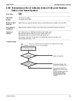
3.74 Transmission Error between Centralized Controller and
Indoor Unit
Error Code
UE
Applicable
Models
All indoor unit models
Central remote controller
Schedule timer
intelligent Touch Controller
Method of Error
Detection
Microcomputer checks if transmission between indoor unit and centralized controller is normal.
Error Decision
Conditions
When transmission is not carried out normally for a certain amount of time
Supposed
Causes
Transmission error between optional controllers for centralized controller and indoor unit
Connector for setting main controller is disconnected.
(or disconnection of connector for independent / combined use changeover switch.)
Defective PCB for central remote controller
Defective indoor unit control PCB
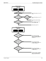
Troubleshooting
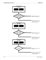
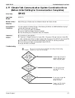
Is the
power supply of
the indoor unit, on which
the
UE
occurred,
turned ON?
For
VRV
systems,
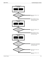
can the setting of
central control group No. be
made in one and the
same refrigerant
system?
Has
the setting of
central control group
No. been made with the
indoor unit on which the
UE
occurred?
Can the
setting of central
control group No be
made?
Check
the indoor
unit for which
UE
is displayed. Is the
transmission error
UE
caused on all
indoor units?
Was the
central control
group No. for indoor
unit changed?
Make correct setting of the
central control group No.
Check outdoor units to which
the refrigerant system is
connected.
Check whether or not there are
no problems with the
transmission wiring length,
types of cables and wires,
number of units connected, and
others. If no problems, replace
the indoor unit control PCB.
NO
YES
YES
NO
NO
YES
Make sure there are no
hazardous situations, and
then turn ON the power
supply.
NO
NO
YES
YES
NO
YES
Reset the power supplies of
every centralized controller.
For the intelligent Touch
Controller, register the air
conditioner again while in
DIII-NET test run menu.
Caution
Be sure to turn off the power switch before connecting or disconnecting
connectors, or parts may be damaged.
A
Go to the next page.
Summary of Contents for REYQ-XA
Page 1: ...Service Manual SiUS371901E REYQ72 456XATJU REYQ72 456XAYDU REYQ72 432XAYCU Heat Recovery 60 Hz...
Page 415: ...SiUS371901E Wiring Diagrams Appendix 402 REYQ144 168XATJU 2D119206A...
Page 416: ...Wiring Diagrams SiUS371901E 403 Appendix REYQ72 96 120XAYDU 2D119207B...
Page 417: ...SiUS371901E Wiring Diagrams Appendix 404 REYQ144 168XAYDU 2D119208B...
Page 418: ...Wiring Diagrams SiUS371901E 405 Appendix REYQ72 96 120 144 168XAYCU 2D119209A...
Page 421: ...SiUS371901E Wiring Diagrams Appendix 408 FXZQ05 07 09 12 15 18TAVJU 3D110443A...
Page 423: ...SiUS371901E Wiring Diagrams Appendix 410 FXEQ07 09 12 15 18 24PVJU 3D098557A...
Page 425: ...SiUS371901E Wiring Diagrams Appendix 412 FXSQ05 07 09 12 15 18 24 30 36 48 54TAVJU C 3D110467C...
Page 426: ...Wiring Diagrams SiUS371901E 413 Appendix FXMQ07 09 12 15 18 24 30 36 48 54PBVJU 3D093209B...
Page 428: ...Wiring Diagrams SiUS371901E 415 Appendix FXHQ12 24 36MVJU 3D048116C...
Page 429: ...SiUS371901E Wiring Diagrams Appendix 416 FXAQ07 09 12 18 24PVJU C 3D075354D...
Page 435: ...SiUS371901E Wiring Diagrams Appendix 422 VAM1200GVJU 3D073270D...
Page 437: ...SiUS371901E Wiring Diagrams Appendix 424 1 4 2 Multi Branch Selector Unit BS4Q54TVJ 3D089123B...
Page 438: ...Wiring Diagrams SiUS371901E 425 Appendix BS6 8Q54TVJ 2D089122B...
Page 439: ...SiUS371901E Wiring Diagrams Appendix 426 BS10 12Q54TVJ 2D089121B...
Page 440: ...Revision History Month Year Version Revised contents 04 2019 SiUS371901E First edition...

