Test Operation
SiUS371901E
223
Field Settings and Test Operation
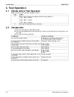
3. Test Operation
3.1
Checks before Test Operation
Before carrying out a test operation, proceed as follows:
3.2
Checkpoints
To carry out a test operation, check the following:
Check that the temperature setting of the remote controller is at the lowest level in cooling mode or use
test mode.
Go through the following checklist:
Step
Action
1
Make sure the voltage at the primary side of the safety breaker is:
187 - 253 V (-XATJU)
or
416 - 508 V (-XAYDU)
or
518 - 632 V (-XAYCU)
2
Fully open the liquid and the gas stop valve.
Checkpoints
Cautions or warnings
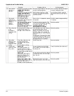
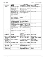
Are all units securely installed?
z
Dangerous for turning over during storm
z
Possible damage to pipe connections
Is the ground wire installed according to the applicable
local standard?
Dangerous if electric leakage occurs
Are all air inlets and outlets of the indoor and outdoor units
unobstructed?
z
Poor cooling
z
Poor heating
Does the drain flow out smoothly?
Water leakage
Is piping adequately heat-insulated?
Water leakage
Have the connections been checked for gas leakage?
z
Poor cooling
z
Poor heating
z
Stop
Is the supply voltage conform to the specifications on the
name plate?
Incorrect operation
Are the cable sizes as specified and according to local
regulations?
Damage of cables
Are the remote controller signals received by the unit?
No operation
Summary of Contents for REYQ-XA
Page 1: ...Service Manual SiUS371901E REYQ72 456XATJU REYQ72 456XAYDU REYQ72 432XAYCU Heat Recovery 60 Hz...
Page 415: ...SiUS371901E Wiring Diagrams Appendix 402 REYQ144 168XATJU 2D119206A...
Page 416: ...Wiring Diagrams SiUS371901E 403 Appendix REYQ72 96 120XAYDU 2D119207B...
Page 417: ...SiUS371901E Wiring Diagrams Appendix 404 REYQ144 168XAYDU 2D119208B...
Page 418: ...Wiring Diagrams SiUS371901E 405 Appendix REYQ72 96 120 144 168XAYCU 2D119209A...
Page 421: ...SiUS371901E Wiring Diagrams Appendix 408 FXZQ05 07 09 12 15 18TAVJU 3D110443A...
Page 423: ...SiUS371901E Wiring Diagrams Appendix 410 FXEQ07 09 12 15 18 24PVJU 3D098557A...
Page 425: ...SiUS371901E Wiring Diagrams Appendix 412 FXSQ05 07 09 12 15 18 24 30 36 48 54TAVJU C 3D110467C...
Page 426: ...Wiring Diagrams SiUS371901E 413 Appendix FXMQ07 09 12 15 18 24 30 36 48 54PBVJU 3D093209B...
Page 428: ...Wiring Diagrams SiUS371901E 415 Appendix FXHQ12 24 36MVJU 3D048116C...
Page 429: ...SiUS371901E Wiring Diagrams Appendix 416 FXAQ07 09 12 18 24PVJU C 3D075354D...
Page 435: ...SiUS371901E Wiring Diagrams Appendix 422 VAM1200GVJU 3D073270D...
Page 437: ...SiUS371901E Wiring Diagrams Appendix 424 1 4 2 Multi Branch Selector Unit BS4Q54TVJ 3D089123B...
Page 438: ...Wiring Diagrams SiUS371901E 425 Appendix BS6 8Q54TVJ 2D089122B...
Page 439: ...SiUS371901E Wiring Diagrams Appendix 426 BS10 12Q54TVJ 2D089121B...
Page 440: ...Revision History Month Year Version Revised contents 04 2019 SiUS371901E First edition...


