


SiUS371901E
Field Settings for Indoor Unit
Field Settings and Test Operation
176
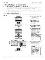
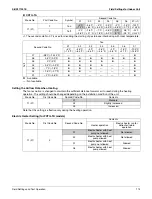
Automatic Airflow Adjustment
The volume of blow-off air is automatically adjusted to the rated quantity.
Make settings before performing the test operation of the outdoor unit.
Setting procedure
(1) Make sure that electric wiring and duct construction have been completed.
In particular, if the closing damper is installed on the way of the duct, make sure that it is open. In addition,
make sure that a field-supplied air filter is installed within the air passageway on the suction port side.
(2) If there are multiple blow-off and suction ports, adjust the throttle part so that the airflow volume ratio of each
suction/blow-off port conforms to the designed airflow volume ratio. In that case, operate the unit with the
operation mode "fan". When you want to change the airflow rate, adjust it by pressing the airflow rate control
button to select High, Middle or Low.
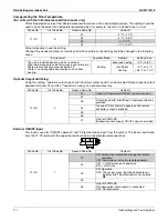
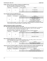
(3) Make settings to adjust the airflow rate automatically.
After setting the operation mode to "fan", enter the field setting mode while operation is stopped and then
select the Mode No. 11 (21), set the First Code No. to
7
and the Second Code No. to
03
.
(4) After setting, return to the basic screen (to the normal mode in the case of a wireless remote controller) and
press the ON/OFF button. Fan operation for automatic airflow adjustment will start with the operation lamp
turned ON. Do not adjust the throttle part of the suction and blow-off ports during automatic adjustment. After
operation for approximately one to fifteen minutes, airflow adjustment automatically stops with the operation
lamp turned OFF.
(5) After operation stopped, make sure that the Second Code No. is set to
02
as in the following table by indoor
unit with the Mode No. 11 (21). If operation does not stop automatically or the Second Code No. is not set to
02
, return to the step (3) above to make settings again.
Notes:
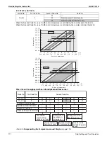
1. Make sure that the external static pressure is within the range of specifications before making settings. If it is
outside the range, automatic adjustment fails, which may cause an insufficient airflow volume or leakage of
water.
2. If the air passageway including duct or blow-off ports is changed after automatic adjustment, make sure to
perform automatic airflow adjustment again.
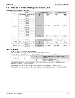
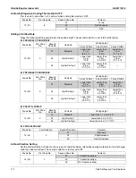
Compensating the Temperature around People
(For units with the infrared presence/floor sensor only)
Change the ratio between the suction air temperature and floor temperature used to calculate the temperature
around human.
The temperature around human is calculated using the values of the suction air thermistor and the infrared floor
sensor. The factory setting is Normal (the average value of the suction air temperature and the floor temperature
is applied). However, the rate at which the suction air thermistor and the infrared floor sensor affect the
temperature around human can be changed with this setting.
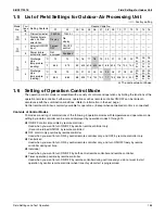
• To reflect the effect of the temperature around the ceiling, select the "Priorities given on the suction air
temperature" (the Second code No.
02
).
• To reflect the effect of the temperature around the floor, select the "Priorities given on the floor temperature"
(the Second code No.
04
).
• The infrared presence/floor sensor can be disabled by selecting "Suction air temperature only" (the Second
code No.
01
).
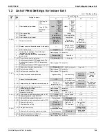
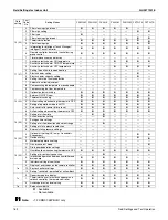
Mode No.
First Code No.
Second Code No.
Contents
11 (21)
7
01
OFF
02
Completion of airflow adjustment
03
Start of airflow adjustment
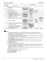
Mode No.
First Code No.
Second Code No.
Contents
11 (21)
8
01
Suction air temperature only
02
Priorities given on the suction air temperature
03
Standard
04
Priorities given on the floor temperature
Summary of Contents for REYQ-XA
Page 1: ...Service Manual SiUS371901E REYQ72 456XATJU REYQ72 456XAYDU REYQ72 432XAYCU Heat Recovery 60 Hz...
Page 415: ...SiUS371901E Wiring Diagrams Appendix 402 REYQ144 168XATJU 2D119206A...
Page 416: ...Wiring Diagrams SiUS371901E 403 Appendix REYQ72 96 120XAYDU 2D119207B...
Page 417: ...SiUS371901E Wiring Diagrams Appendix 404 REYQ144 168XAYDU 2D119208B...
Page 418: ...Wiring Diagrams SiUS371901E 405 Appendix REYQ72 96 120 144 168XAYCU 2D119209A...
Page 421: ...SiUS371901E Wiring Diagrams Appendix 408 FXZQ05 07 09 12 15 18TAVJU 3D110443A...
Page 423: ...SiUS371901E Wiring Diagrams Appendix 410 FXEQ07 09 12 15 18 24PVJU 3D098557A...
Page 425: ...SiUS371901E Wiring Diagrams Appendix 412 FXSQ05 07 09 12 15 18 24 30 36 48 54TAVJU C 3D110467C...
Page 426: ...Wiring Diagrams SiUS371901E 413 Appendix FXMQ07 09 12 15 18 24 30 36 48 54PBVJU 3D093209B...
Page 428: ...Wiring Diagrams SiUS371901E 415 Appendix FXHQ12 24 36MVJU 3D048116C...
Page 429: ...SiUS371901E Wiring Diagrams Appendix 416 FXAQ07 09 12 18 24PVJU C 3D075354D...
Page 435: ...SiUS371901E Wiring Diagrams Appendix 422 VAM1200GVJU 3D073270D...
Page 437: ...SiUS371901E Wiring Diagrams Appendix 424 1 4 2 Multi Branch Selector Unit BS4Q54TVJ 3D089123B...
Page 438: ...Wiring Diagrams SiUS371901E 425 Appendix BS6 8Q54TVJ 2D089122B...
Page 439: ...SiUS371901E Wiring Diagrams Appendix 426 BS10 12Q54TVJ 2D089121B...
Page 440: ...Revision History Month Year Version Revised contents 04 2019 SiUS371901E First edition...