background image

LREQ5~20B7Y1

Air cooled refrigeration condensing unit

4PW74302-1 – 2012.06

Installation manual

8

2.

Removing Pinch Piping

WARNING

Never remove the pinched piping by brazing.
Failure to observe the instructions in procedure below properly may 
result in property damage or personal injury, which may be serious 
depending on the circumstances.

CAUTION

Use the following procedure to remove the pinched piping:
1

Remove the valve lid and make sure that the stop 
valves are fully closed.

2

Connect a charge hose to service ports of all stop valves.

3

Recover gas and oil from the pinched piping by using a recovery 
unit. 

4

When all gas and oil is recovered from the pinched piping, 
disconnect the charge hose and close the service ports.
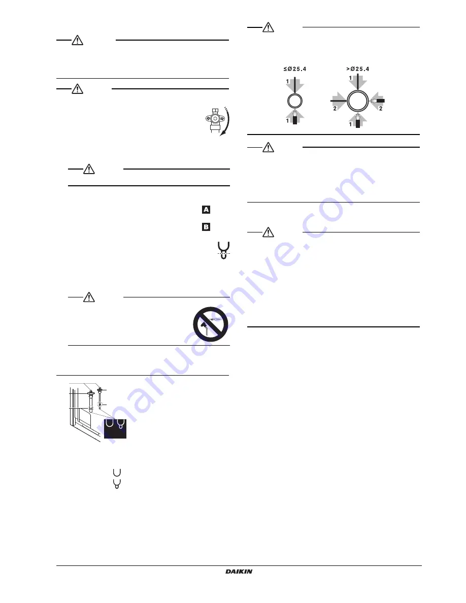
5

In case the pinched piping lower part looks like detail 

 in the 

figure below, follow instructions as per procedure steps 7+8.

In case the pinched piping lower part looks like detail 

 in the 

figure below, follow instructions as per procedure steps 6+7+8.

6

Cut off the lower part of the smaller pinched piping with an 
appropriate tool (e.g. a pipe cutter, a pair of nippers, ...) so 
that a cross-section is open, allowing remaining oil to drip 
out in case the recovery was not complete.
Wait until all oil is dripped out.

7

Cut the pinched piping off with a pipe cutter just above the brazing 
point or just above the marking in case there is no brazing point. 

8

Wait until all oil is dripped out in case the recovery was not 
complete, and only then proceed with connection of the field 
piping.

1 Service port
2 Stop valve
3 Point of pipe cutting just above brazing point or above marking
A Pinched piping 

B Pinched piping 

CAUTION

Precautions when connecting field piping.

• Perform brazing at the gas stop valve before brazing at the liquid 

stop valve.

• Add brazing material as shown in the figure.

CAUTION

• Be sure to use the supplied accessory pipes when carrying out 

piping work in the field.

• Be sure that the field installed piping does not touch other pipes, 

the bottom panel or side panel. Especially for the bottom and side 
connection, be sure to protect the piping with suitable insulation, to 
prevent it from coming into contact with the casing.

Operation Method of Shutoff Valves

Follow the instructions below when operating each shutoff valve.

CAUTION

• Do not open the shutoff valve until the steps specified in 

8-3 Checking of device and installation conditions

” is 

completed.
Do not leave the shutoff valve opened without turning the power 
on, otherwise refrigerant may be condensed in the compressor and 
the insulation of the main power supply circuit may be degraded.

• Be sure to use an exclusive tool to handle the shutoff valve. The 

shutoff valve is not of back sheet type. Excessive force imposed 
may break the valve.

• Use a charge hose when using the service port.
• Make sure that there is no refrigerant gas leakage after the valve 

cover and cap are securely tightened.

CAUTION

Do not vent gases into the atmosphere.

CAUTION

Never remove the pinched piping by brazing.

1

2

3

2

3

B

A

Summary of Contents for LREQ5B7Y1

Page 1: ...INSTALLATION MANUAL LREQ5B7Y1 LREQ6B7Y1 LREQ8B7Y1 LREQ10B7Y1 LREQ12B7Y1 LREQ15B7Y1 LREQ20B7Y1 Air cooled refrigeration condensing unit...

Page 2: ...jennom positiv bed mmelse av B if lge Sertifikat C som det fremkommer i den Tekniske Konstruksjonsfilen D og gjennom positiv bed mmelse av E Anvendt modul F G Risikokategori H Se ogs neste side 13 jot...

Page 3: ...PS vastav k llastunud temperatuur M C Jahutusaine N Surve turvaseadme seadistus P bar Tootmisnumber ja tootmisaasta vaadake mudeli andmeplaati 21 PS K bar TS TSmin L C TSmax PS M C N P bar 22 Maksima...

Page 4: ...on manual Improper installation may result in water leakage electric shocks or fire When installing the unit in a small room take measures so that the refrigerant may not exceed the limiting concentra...

Page 5: ...ons be observed for keeping the system clean dry and tightly sealed Read the chapter 6 REFRIGERANT PIPING on page 5 carefully and follow these procedures correctly A Clean and dry Strict measures must...

Page 6: ...disturb anyone 3 The foundation is strong enough to support the weight of the unit and the floor is flat to prevent vibration and noise generation 4 The piping length between the outdoor unit and the...

Page 7: ...ary to take measures against leakage See Engineering Data for details 4 HANDLING THE UNIT 1 Decide on the transportation route 2 If a forklift is to be used pass the forklift arms through the large op...

Page 8: ...ng refrigerant piping heat exchangers Keep the following points in mind for the reuse of existing refrigerant piping heat exchangers A malfunction may result if there is deficiency Do not use the exis...

Page 9: ...oor unit H 10 m Note A trap is required at 5 m intervals from outdoor unit d1 e B d2 C c D1 F E f D2 A b a Outdoor unit Showcase Unit cooler Gas piping Liquid piping H Refrigerant piping size Unit mm...

Page 10: ...e operation manual of the dryer 6 5 Connecting the refrigerant piping CAUTION In addition to gas and liquid shutoff valves this unit has a maintenance shutoff valve see diagram below Do not operate th...

Page 11: ...dripped out in case the recovery was not complete and only then proceed with connection of the field piping 1 Service port 2 Stop valve 3 Point of pipe cutting just above brazing point or above markin...

Page 12: ...apply a screw lock agent to the screw thread Do not apply a screw lock agent for flare nut use to the sealing part Be sure to tighten the cap securely after the work Refer to Operation Method of Shuto...

Page 13: ...eriorate power factor improvement effect but also may cause capacitor abnormal heating accident due to high frequency waves Only proceed with wiring work after blocking off all power Always ground wir...

Page 14: ...eakage Be sure to connect the power wiring to the power wiring terminal block and secure it as described in 7 2 Procedure for incoming wiring on page 11 Do not connect the power supply to the terminal...

Page 15: ...EN IEC61000 3 11 1 provided that the system impedance Zsys is less than or equal to Zmax and EN IEC61000 3 12 2 provided that the short circuit power Ssc is greater than or equal to the minimum Ssc va...

Page 16: ...y the washer Otherwise the earth wire may not contact sufficiently and the earthing effect of the wire may be lost Do not finish strand wire with solder 7 4 Procedure for wiring inside units Referring...

Page 17: ...red to have passed if there is no decrease in the pressure over a period of 24 hours If there is a decrease in the pressure check for and repair leaks Vacuum drying Operate the vacuum pump for more th...

Page 18: ...of piping material on page 6 2 Make sure insulation work is done See 8 2 Thermal insulation work on page 14 3 Make sure there is no faulty refrigerant piping See 6 REFRIGERANT PIPING on page 5 9 CHEC...

Page 19: ...ling 1The cylinder s internal pressure will drop when there is little refrigerant remaining in the cylinder making it impossible to charge the unit even if the liquid shutoff valve opening is adjusted...

Page 20: ...lay The contents of a LED H2P display are as follows How to check malfunction code By operating the pushbutton switches on the PCB malfunction code items can be displayed on the condensing unit 1 Make...

Page 21: ......

Page 22: ......

Page 23: ......

Page 24: ...4PW74302 1 2012 06 Copyright 2012 Daikin 4PW74302 1 00000003...

Reviews: