The Controller for the EUWA/Y15-30HC(Z) Chillers
ESIE98–06A
2–34
Part 2 – Functional Description
3
1
2
4
5
Screen 3
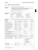
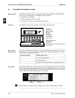
This screen provides the ability to modify the thermostat parameters:
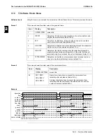
The figure below shows the thermostat parameters:
Screen 4 (optional)
You can install an optional PCB to control the unit from a PC (this feature is under development). The
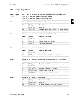
BMS (Building Management System) parameters provide communication between the unit and the
PC. This screen provides the ability to activate the PC control mode and to modify following BMS
settings:
This screen will only be displayed if the optional BMS PCB is installed (under development).
Screen 5
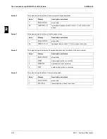
This screen provides the ability to assign password protection to the set points menu:
Line n°
Display
Description
Lower
limit
Upper
limit
Step
Default
1
THERM. SETTINGS
screen title
2
STEPS
number of thermo-
stat steps
1
3
1
2
2
STPL
(°C)
step length (a)
0.4
2.0
0.1
1.5
3
STEPDIFFERENCE
(°C)
step difference (b)
0.2
0.8
0.1
0.5
4
LOADUP
(s)
load up time
15
300
1
180
4
LOADDOWN
(s)
loaddown time
15
300
1
20
c
a
b
d
Step 0
Step 1
Step 2
Step 3
inlet water temperature
Line n°
Display
Description
Possible
settings
1
BMS -SETTINGS
screen title
2
BMS CONTROL ALLOWED
To select the PC control mode.
Y/N
3
UNIT ADDRESS
Used to address the unit if more than one
unit is connected to the PC.
4
PROTOCOL
Indicates the communication protocol
Line n°
Display
Description
Possible settings
1
SETPOINT - PASSWORD
screen title
2
PASSWORD NEEDED TO
CHANGE SETPOINTS
Assign password protec-
tion to set points menu.
Y/N
Summary of Contents for EUWA/Y5-30HB/C(Z)
Page 2: ......
Page 8: ...Introduction ESIE98 06A vi 3 1 4 5...
Page 10: ...ESIE98 06A 1 2 Part 1 System Outline 3 1 1 4 5...
Page 28: ...General Outline ESIE98 06A 1 20 Part 1 System Outline 3 1 1 4 5...
Page 36: ...Piping Layout ESIE98 06A 1 28 Part 1 System Outline 3 1 1 4 5...
Page 52: ...ESIE98 06A Wiring Layout Part 1 System Outline 1 44...
Page 58: ...ESIE98 06A 2 2 Part 2 Functional Description 3 1 2 4 5...
Page 100: ...ESIE98 06A 3 2 Part 3 Troubleshooting 3 1 3 4 5...
Page 134: ...Troubleshooting ESIE98 06A 3 36 Part 3 Troubleshooting 3 1 3 4 5...
Page 136: ...ESIE98 06A 4 2 Part 4 Commissioning and Test Run 3 1 4 5...
Page 142: ...Pre Test Run Checks ESIE98 06A 4 8 Part 4 Commissioning and Test Run 3 1 4 5...

