ESIE98–06A
Piping Layout
Part 1 – System Outline
1–25
3
1
4
5
1
2.4
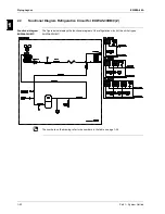
Functional Diagram Refrigeration Circuit for EUWY5-30HB/C,
EUWA5-30HB/C with Glycol Application
Functional diagram
EUWY5-30HB/C
The figure below displays the functional diagram of the refrigeration circuit of the chiller types
EUWY5-30HB/C:
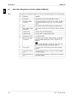
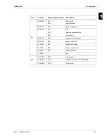
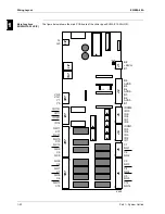
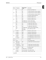
The numbers on the drawing refer to the numbers in the table on page 1-27.
SHP
MC
YRV
p >
EUWY15-20H
R7T
t >
R4T
t <
R5T
t <
t <
EUWY25-30H
R7T
t >
t <
R4T
t <
R5T
t <
R6T
t <
R3T
R4T
t >
t <
t <
EUWY5-10H
2
4
9
5
5
8
1
13
12
10
11
7
3
4918
cooling
heating
evaporator
condenser
evaporator
condenser
14
Summary of Contents for EUWA/Y5-30HB/C(Z)
Page 2: ......
Page 8: ...Introduction ESIE98 06A vi 3 1 4 5...
Page 10: ...ESIE98 06A 1 2 Part 1 System Outline 3 1 1 4 5...
Page 28: ...General Outline ESIE98 06A 1 20 Part 1 System Outline 3 1 1 4 5...
Page 36: ...Piping Layout ESIE98 06A 1 28 Part 1 System Outline 3 1 1 4 5...
Page 52: ...ESIE98 06A Wiring Layout Part 1 System Outline 1 44...
Page 58: ...ESIE98 06A 2 2 Part 2 Functional Description 3 1 2 4 5...
Page 100: ...ESIE98 06A 3 2 Part 3 Troubleshooting 3 1 3 4 5...
Page 134: ...Troubleshooting ESIE98 06A 3 36 Part 3 Troubleshooting 3 1 3 4 5...
Page 136: ...ESIE98 06A 4 2 Part 4 Commissioning and Test Run 3 1 4 5...
Page 142: ...Pre Test Run Checks ESIE98 06A 4 8 Part 4 Commissioning and Test Run 3 1 4 5...


