ESIE98–06A
Functional Control
Part 2 – Functional Description
2–11
3
2
4
5
1
1.6
Thermostat Control
Two different
thermostat controls
The thermostat control in chiller types EUWA/Y5-10HB(Z) differs from that in chiller types
EUWA/Y15-30HC(Z).
Functional diagram
EUWA/Y5-10HB(Z)
Controller
EUWA/Y5-10HB(Z)
The limit values of the step difference are given below:
Functional diagram
EUWA/Y15-30HC(Z)
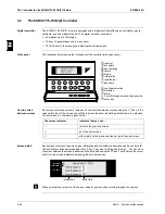
The figure below shows the thermostat parameters for chiller types EUWA/Y15-30HC(Z):
Controller
EUWA/Y15-30HC(Z)
Screen 3 of the user settings menu provides the ability to modify the thermostat parameters:
c: cooling set point
d: heating set point
c
d
compressor
ON
OFF
inlet water temperature
Description
Lower limit
Upper limit
Step
Default
step difference
0.3
19.9
0.1
3.0
c
a
b
d
Step 0
Step 1
Step 2
Step 3
inlet water temperature
a: step length
b: step difference
c: cooling set point
d: heating set point
Line n°
Display
Description
Lower
limit
Upper
limit
Step
Default
1
THERM. SETTINGS
screen title
2
STEPS
number of thermostat
steps
1
3
1
2
2
STPL
(°C)
step length (a)
0.4
2.0
0.1
1.5
3
STEPDIFFERENCE
(°C)
step difference (b)
0.2
0.8
0.1
0.5
4
LOADUP
(s)
load up time
15
300
1
180
4
LOADDOWN
(s)
load down time
15
300
1
20
Summary of Contents for EUWA/Y5-30HB/C(Z)
Page 2: ......
Page 8: ...Introduction ESIE98 06A vi 3 1 4 5...
Page 10: ...ESIE98 06A 1 2 Part 1 System Outline 3 1 1 4 5...
Page 28: ...General Outline ESIE98 06A 1 20 Part 1 System Outline 3 1 1 4 5...
Page 36: ...Piping Layout ESIE98 06A 1 28 Part 1 System Outline 3 1 1 4 5...
Page 52: ...ESIE98 06A Wiring Layout Part 1 System Outline 1 44...
Page 58: ...ESIE98 06A 2 2 Part 2 Functional Description 3 1 2 4 5...
Page 100: ...ESIE98 06A 3 2 Part 3 Troubleshooting 3 1 3 4 5...
Page 134: ...Troubleshooting ESIE98 06A 3 36 Part 3 Troubleshooting 3 1 3 4 5...
Page 136: ...ESIE98 06A 4 2 Part 4 Commissioning and Test Run 3 1 4 5...
Page 142: ...Pre Test Run Checks ESIE98 06A 4 8 Part 4 Commissioning and Test Run 3 1 4 5...


