Functional Control
ESIE98–06A
2–10
Part 2 – Functional Description
3
1
2
4
5
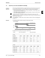
Defrost circuit
combination
EUWY15-30HC
When one of the circuits of chillers with more than one refrigeration circuit (EUWY15-30HC) performs
a defrost:
■
Circuits 2 and 3 will influence each other in such a way that one circuit is switched off when the
other circuit performs a defrost.
■
Circuit 1 will be independent of the other two.
Circuit layout
The following table gives information concerning the horsepower per circuit:
Defrost
possibilities
The first column in the following table shows the circuits that are in defrost. The other columns describe
the status of the circuits:
D = the circuit performs a defrost
O = the circuit is switched off
C = the circuit continues its normal operation
Chiller type
Circuit 1
Circuit 2
Circuit 3
15H
10 HP
5 HP
—
20H
10 HP
10 HP
—
25H
10 HP
10 HP
5 HP
30H
10 HP
10 HP
10 HP
Circuit(s) in defrost
Circuit 1
Circuit 2
Circuit 3
circuit 1
D
C
C
circuit 2
C
D
O
circuit 3
C
O
D
circuit 1+3
D
O
D
circuit 1+2
D
D
O
Summary of Contents for EUWA/Y5-30HB/C(Z)
Page 2: ......
Page 8: ...Introduction ESIE98 06A vi 3 1 4 5...
Page 10: ...ESIE98 06A 1 2 Part 1 System Outline 3 1 1 4 5...
Page 28: ...General Outline ESIE98 06A 1 20 Part 1 System Outline 3 1 1 4 5...
Page 36: ...Piping Layout ESIE98 06A 1 28 Part 1 System Outline 3 1 1 4 5...
Page 52: ...ESIE98 06A Wiring Layout Part 1 System Outline 1 44...
Page 58: ...ESIE98 06A 2 2 Part 2 Functional Description 3 1 2 4 5...
Page 100: ...ESIE98 06A 3 2 Part 3 Troubleshooting 3 1 3 4 5...
Page 134: ...Troubleshooting ESIE98 06A 3 36 Part 3 Troubleshooting 3 1 3 4 5...
Page 136: ...ESIE98 06A 4 2 Part 4 Commissioning and Test Run 3 1 4 5...
Page 142: ...Pre Test Run Checks ESIE98 06A 4 8 Part 4 Commissioning and Test Run 3 1 4 5...


