I N S T A L L A T I O N , O P E R A T I O N A N D M A I N T E N A N C E I N S T R U C T I O N S
Variable-Speed Air-Cooled Screw Chillers
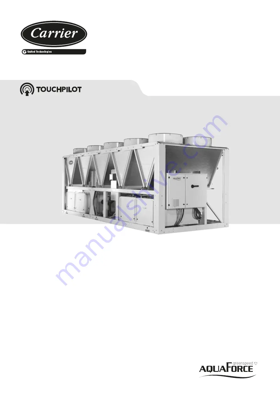
30XAV 500 - 1150
Original document
Nominal cooling capacity : 500 - 1150 kW
50 Hz
Page 1: ... S TA L L AT I O N O P E R AT I O N A N D M A I N T E N A N C E I N S T R U C T I O N S Variable Speed Air Cooled Screw Chillers 30XAV 500 1150 Original document Nominal cooling capacity 500 1150 kW 50 Hz ...
Page 2: ...ower connection disconnect switch 18 5 4 Recommended wire sections 18 5 5 Power cable entry 18 5 6 Field control wiring 19 5 7 Electric and power reserve for the user 19 6 APPLICATION DATA 20 6 1 Operating range 20 6 2 Minimum chilled water flow units without hydronic module 20 6 3 Maximum chilled water flow units without hydronic module 20 6 4 Variable flow evaporator 21 6 5 System minimum water ...
Page 3: ...s 30 9 10 Fans 30 9 11 Electronic expansion valve EXV 31 9 12 Moisture indicator 31 9 13 Filter drier 31 9 14 Sensors 31 9 15 Service valve option 92 32 9 16 Variable frequency drive 32 10 OPTIONS 33 11 STANDARD MAINTENANCE 35 11 1 Level 1 maintenance 35 11 2 Level 2 maintenance 35 11 3 Level 3 or higher maintenance 35 11 4 Tightening torques for the main electrical connections 36 11 5 Tightening ...
Page 4: ...ircuits Check if the original protection plugs are still present at the valve outlets These plugs are generally made of plastic and should not be used If they are still present please remove them Install devices at the valve outlets or drain piping that prevent the penetration of foreign bodies dust building debris etc and atmospheric agents water can form rust or ice These devices as well as the ...
Page 5: ...e pressure equipment can be recycled in whole or in part After use they may contain refrigerant vapours and oil residue Some parts are painted 1 3 Maintenance safety considerations Carrier recommends the following drafting for a logbook the table below should not be considered as reference and does not involve Carrier responsibility Intervention Name of the commissioning engineer Applicable nation...
Page 6: ...n similar criteria do not exist in the national regulation PROTECTION DEVICE CHECKS If no national regulations exist check the protection devices on site in accordance with standard EN 378 once a year for the high pressure switches every five years for external relief valves The company or organisation that conducts a pressure switch test must establish and implement a detailed procedure to fix Sa...
Page 7: ...ety goggles and safety gloves Wash any spills from the skin with soap and water If liquid refrigerant enters the eyes immediately and abundantly flush the eyes with water and consult a doctor The accidental releases of the refrigerant due to small leaks or significant discharges following the rupture of a pipe or an unexpected release from a relief valve can cause frostbites and burns to personnel...
Page 8: ...rrent drawn Maximum power input Unit net weight Confirm that all accessories ordered for on site installation have been delivered and are complete and undamaged The unit must be checked periodically during its whole operating life to ensure that no shocks handling accessories tools etc have damaged it If necessary damaged parts must be repaired or replaced See also chapter 8 Standard maintenance 2...
Page 9: ...es instruction manuals provided by the manufacturer to comply with the regulations are present Verify the free passage of access and safety routes Check that ventilation in the plant room is adequate Check that refrigerant detectors are present Verify the instructions and directives to prevent the venting removal of refrigerant gases that are harmful to the environment Verify the installation of c...
Page 10: ... 6 100A 100C 107 refer to the certified drawing Air outlet do not obstruct Power supply and control connection C Control circuit connection for option 158 NOTES Drawings are not contractually binding Before designing an installation consult the certified dimensional drawings available on request For the positioning of the fixing points weight distribution and centre of gravity coordinates please r...
Page 11: ...ied drawing Air outlet do not obstruct Power supply and control connection C Control circuit connection for option 158 NOTES Drawings are not contractually binding Before designing an installation consult the certified dimensional drawings available on request For the positioning of the fixing points weight distribution and centre of gravity coordinates please refer to the dimensional drawings If ...
Page 12: ...fied drawing Air outlet do not obstruct Power supply and control connection C Control circuit connection for option 158 NOTES Drawings are not contractually binding Before designing an installation consult the certified dimensional drawings available on request For the positioning of the fixing points weight distribution and centre of gravity coordinates please refer to the dimensional drawings If...
Page 13: ...at the time of purchase can be added H S h Wall Anti vibration mounts Legend All dimensions are given in mm Required clearances for maintenance see note Recommended space for evaporator tube removal Water inlet for standard unit For options 5 6 100A 100C 107 refer to the certified drawing Water outlet for standard unit For options 5 6 100A 100C 107 refer to the certified drawing Air outlet do not ...
Page 14: ...0 10 10 10 Condensers All aluminium Micro Channel Heat Exchanger MCHE Fans Standard unit Axial FLYING BIRD IV fans with rotating shroud Quantity 9 10 12 14 16 18 20 Maximum total air flow l s 40608 45120 54144 63168 72192 81216 90240 Maximum rotational speed rps 15 7 15 7 15 7 15 7 15 7 15 7 15 7 Evaporator Flooded multi pipe type Water volume l 75 90 90 110 120 134 146 Max water side operating pr...
Page 15: ...peration with maximum unit power input Values obtained at operation with maximum unit power input Values given on the unit nameplate When the machines are equipped with two power supplies circuit 1 is intended to supply the refrigerant circuit A and circuit 2 supplies the refrigerant circuit B Values obtained at standard Eurovent operating condition Air 35 C water 12 7 C 4 3 Short circuit stabilit...
Page 16: ...nd nominal voltage 91 3 91 3 1 Nominal efficiency at 75 rated load and nominal voltage 91 4 91 4 1 Nominal efficiency at 50 rated load and nominal voltage 90 3 90 3 2 Efficiency level IE3 IE3 3 Year of manufacture This information varies depending on the manufacturer and model at the time of incorporation Please refer to the motor name plates 4 Manufacturer s name and trademark commercial registra...
Page 17: ...must not be connected directly to the unit if necessary use a transformer 4 Overcurrent protection of the power supply conductors is not provided with the unit 5 The factory installed disconnect switch es circuit breaker s is are of a type suitable for power interruption in accordance with EN 60947 3 corresponds to IEC 60947 3 6 The units are designed for connection to TN networks IEC 60364 In IT ...
Page 18: ...o the general disconnect isolator switch are designed for the number and type of wires listed in column 2 of the table on the next page The calculations are based on the maximum machine current see electrical data tables The calculations of favourable and unfavourable cases are based on the maximum current for each unit see electrical data tables For the design the standardised installation method...
Page 19: ... connected the TC transformer ensures a power supply reserve of 1 A under 24 Vac that can be used for the on site control cabling As an option a secondTC transformer powers a 230V 50Hz circuit can be used for charging a laptop battery maximum current 0 8 A A standard CEE7 17 type E connector is provided This circuit is protected by a 10mA earth leakage detector Table of minimum and maximum wire se...
Page 20: ...t in operation 3 3 15 NOTE The use of brine or antifreeze protection option is required if the water outlet temperature is below 4 C Condenser air temperature C Storage 20 C 68 Operation Standard unit 20 C 50 NOTE If the air temperature is below 0 C a glycol water solution or the freeze protection option must be used According to the type of installation and air temperature Operating at partial lo...
Page 21: ...the nominal system cooling capacity kW at the nominal operating conditions of the installation This volume is necessary for stable operation and accurate temperature control It is often necessary to add a buffer water tank to the circuit in order to achieve the required volume The tank must itself be internally baffled in order to ensure proper mixing of the liquid water or brine Refer to the exam...
Page 22: ...month the complete circuit must be placed under nitrogen charge to avoid any risk of corrosion by differential aeration CAUTION Filling completing and draining the water circuit charge must be done by qualified personnel using the air purges and materials that are suitable for the products Charging and removing heat exchange fluids should be done with devices that must be included on the water cir...
Page 23: ...93 3 Relief valve 4 Available pressure water pump 5 Water drain valve 6 Flow switch for the evaporator 7 Evaporator 8 Evaporator heater for freeze protection option 41A 41B 9 Heater for freeze protection of hydronic module option 41 B 10 Air purge evaporator 11 Water purge evaporator 12 Pressure sensor 13 Water temperature probe Installation components 14 Air purge 15 Flexible connection 16 Shut o...
Page 24: ...ndatory Elbow mandatory Elbow mandatory Elbow mandatory For installation that requires thicker insulation it is advised to use a pipe reduction or an elbow to avoid the closest component When straight pipe is not possible use an elbow Check elbow connection limitation in the table below Elbow connection XAV 500 600 700 800 950 1050 1150 Standard unit Inlet mm Check dimension Check dimension Check ...
Page 25: ... protected by an antifreeze solution and will not be used during freezing weather conditions draining of the cooler and outdoor piping is mandatory Damage due to freezing is not covered by the warranty 7 5 2 Optional evaporator freeze protection 30XAV In cases where it is not possible to apply the recommendations in paragraph 7 5 1 the units can be equipped with heaters to protect the evaporator a...
Page 26: ...ch unit controls its own water pump If there is only one common pump and in cases with variable flow isolation valves must be installed on each unit They will be activated at the opening and closing controlled by the individual units using the water pump control signals Refer to the 30XAV Touch Pilot control manual for a more detailed explanation WARNING Both units must have option 58 to allow the...
Page 27: ...pumps options 116T 116U 0 20 40 60 80 100 120 140 160 180 200 0 5 10 15 20 25 30 35 40 45 Available static pressure kPa Flow rate L s Low pressure pumps options 116T 116U 600 simple 500 simple 600 dual 500 dual Available static pressure kPa Flow rate L s High pressure pumps options 116R 116S 500 600 0 50 100 150 200 250 300 350 400 0 5 10 15 20 25 30 35 40 45 Available static pressure kPa Flow rat...
Page 28: ...acity calculations Units with hydronic module enable direct monitoring of flow rate and cooling capacity through IHM refer to 30XAV control manual Fluid pressure is measured by pressure sensors fitted at pump inlet and unit outlet The system calculates the flow rate corresponding to measured differential pressure Combined with temperature difference between evaporator inlet and outlet this flow ra...
Page 29: ...file If there are no regulations or to complement them follow the guidance programmes of EN 378 If they exist follow local professional recommendations Regularly inspect the condition of the coating paint to detect blistering resulting from corrosion To do this check a non insulated section of the vessel or joint in the insulation Regularly check for possible presence of impurities e g silicon gra...
Page 30: ...line valve a filter drier two EXVs a plate heat exchanger as well as protection devices seal or valve At the condenser outlet a part of the liquid is expanded via the secondary EXV in one of the heat exchanger port and then returns as gas at the compressor economiser This expansion increases the sub cooling of the bulk of the liquid refrigerant which then flows into the evaporator via the main EXV...
Page 31: ...es 6 Nominal input frequency Hz 50 Nominal voltage V 400 Number of phases 3 Motor included in the application domain of the regulation 640 2009 amendment 4 2014 NO Sales leaflet for exemption Article 1 2 c ii Ambient air temperature for which the motor is specifically designed C 70 9 11 Electronic expansion valve EXV The EXV is equipped with a stepper motor 2785 to 3690 steps depending on the mode...
Page 32: ...th a variable frequency drive that allows adjustment the capacity of the compressor by varying the speed of the motor within the frequency range of 27 5 60 Hz Variable speed is produced by generating a controlled voltage waveform on which both frequency and voltage are adjustable via Pulse Width Modulation The compressor start up stop and the frequency setpoint within the acceptable range is manag...
Page 33: ... water inlet outlet Easy installation on sites with specific requirements Sizes 500 600 950 1050 1150 only HP single pump hydronic module 116R Complete hydronic module equipped with water filter relief valve one high pressure pump and drain valve For more details refer to the dedicated chapter expansion tank not included Easy and fast installation plug play Sizes 500 600 only HP dual pump hydronic...
Page 34: ...lled residential environment requirements and allow its compliancy with emissions level required in category C2 500 1150 230V electrical plug 284 230V AC power supply source provided with plug socket and transformer 180 VA 0 8 Amps Permits connection of a laptop or an electrical device during unit commissioning or servicing 500 1150 Expansion tank 293 6 bar expansion tank in the hydraulic module r...
Page 35: ... inspection for any signs of deterioration 11 2 Level 2 maintenance This level requires specific expertise in electrical hydraulic and mechanical systems The frequency of this maintenance level may be monthly or annual depending on the verification type In these cases the following maintenance operations are recommended Carry out all level 1 operations then At least once a year tighten the power c...
Page 36: ...autions must be applied during an intervention that requires the removal of the power conductors connected to the compressor supply terminals 1 Application torque for tightening the clamp 2 Avoid contact between clamping nuts 3 Clamping nut husk 4 Pod flat 5 Against nut 6 Clamping nut terminal 7 Insulator The tightening nut of terminal 6 supporting the isolator 7 must never be loosened as ist ensu...
Page 37: ...measuring the pressure at the filter service port and the oil pressure port The difference in these two pressures will be the pressure drop across the filter check valve and solenoid valve The pressure drop across the check valve and solenoid valve is approximately 40 kPa 0 4 bar which should be subtracted from the two oil pressure measurements to give the oil filter pressure drop 11 8 3 Compresso...
Page 38: ...as been sized and installed properly Unit ground wire has been connected Electrical circuit protection has been sized and installed properly All terminals are tight All cables and thermistors have been inspected for crossed wires Chilled water pipes are properly connected All plug assemblies are tight The chilled water pump operating with the correct rotation Check the phase sequence of the electr...
Page 39: ...39 ...
Page 40: ...til corrective measures have been taken Check evaporator water loop Water loop volume litres Calculated volume litres 3 25 liters nominal kW capacity for air conditioning 6 5 liters nominal kW capacity for cooling in industrial processes Proper loop volume established Proper loop corrosion inhibitor included litres of Proper loop freeze protection included if required litres of Piping installation...
Page 41: ...the temperatures and pressures have stabilised record the following Evaporator entering water Evaporator leaving water Ambient temperature Circuit A suction pressure Circuit B suction pressure Circuit A discharge pressure Circuit B discharge pressure Circuit A suction temperature Circuit B suction temperature Circuit A discharge temperature Circuit B discharge temperature Circuit A liquid line tem...
Page 42: ... www certiflash com Order No 13552 12 2016 Supersedes order No 13552 07 2015 Manufacturer Carrier SCS Montluel France Manufacturer reserves the right to change any product specifications without notice Printed in the European Union ...