The Controller for the EUWA/Y15-30HC(Z) Chillers
ESIE98–06A
2–40
Part 2 – Functional Description
3
1
2
4
5
Screen 6
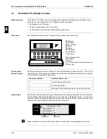
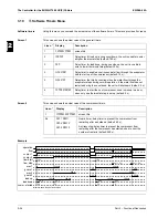
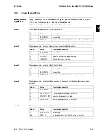
This screen shows the status of the low pressure bypass switches:
Screen 7
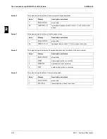
This screen shows the status of the fan speed relays:
Screen 8
This screen shows the alarm and operation indication and the status of the pump contact:
Screen 9
This screen shows the status of the reversing valve:
Line n°
Display
Description and status
1
RELAY OUTPUTS
screen title
2-4
LPBYPASS 1, 2, 3
low pressure bypass switch of circuit 1, 2 or 3: active or not
active
Line n°
Display
Description and status
1
RELAY OUTPUTS
screen title
2-4
FANSP. RY 1, 2, 3
fan speed relay of circuit 1, 2 or 3: active or not active
Line n°
Display
Description and status
1
RELAY OUTPUTS
screen title
2
ALARM
alarm signal: active or not active
3
OPERATION
operation: active or not active
4
PUMP
pump contact: active or not active
Line n°
Display
Description and status
1
RELAY OUTPUTS
screen title
2
REV. VALVE
reversing valve: active or not active
Summary of Contents for EUWA/Y5-30HB/C(Z)
Page 2: ......
Page 8: ...Introduction ESIE98 06A vi 3 1 4 5...
Page 10: ...ESIE98 06A 1 2 Part 1 System Outline 3 1 1 4 5...
Page 28: ...General Outline ESIE98 06A 1 20 Part 1 System Outline 3 1 1 4 5...
Page 36: ...Piping Layout ESIE98 06A 1 28 Part 1 System Outline 3 1 1 4 5...
Page 52: ...ESIE98 06A Wiring Layout Part 1 System Outline 1 44...
Page 58: ...ESIE98 06A 2 2 Part 2 Functional Description 3 1 2 4 5...
Page 100: ...ESIE98 06A 3 2 Part 3 Troubleshooting 3 1 3 4 5...
Page 134: ...Troubleshooting ESIE98 06A 3 36 Part 3 Troubleshooting 3 1 3 4 5...
Page 136: ...ESIE98 06A 4 2 Part 4 Commissioning and Test Run 3 1 4 5...
Page 142: ...Pre Test Run Checks ESIE98 06A 4 8 Part 4 Commissioning and Test Run 3 1 4 5...

