ESIE98–06A
Functional Control
Part 2 – Functional Description
2–13
3
2
4
5
1
1.8
Head Pressure Control for EUWA/Y15-30HC(Z)
Functional
description
The chiller types EUWA/Y15-30HC(Z) are equipped with a fan control to ensure the high pressure
when the ambient temperature is low. When no signal is sent, all fans rotate on high speed.
■
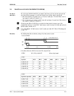
When the temperature decreases until 17°C, relay Ry1 switches on. A first set of fans turns to a
lower speed or switches off (reset at 19°C).
■
When the temperature decreases until 0°C, relay Ry2 switches on. A second set of fans turns to a
lower speed or switches off (reset at 2°C).
All chiller types EUWA/Y15-30HC(Z) are equipped with head pressure control (as part of the
standardized switch box). For the EUWY, head pressure control is not used to its full extend while its
operation range is limited to 15°C.
In the wiring diagram, this head pressure control is positioned in block J22. Refer to ‘Wiring Diagrams’
on page 1-34.
Illustration
The following illustration clarifies the working of the head pressure control:
In the tables below you will find an overview of the relay and fans:
STEP 0
Ry1=OFF and Ry2=OFF
all fans at high speed
STEP 1
Ry1=ON
M11F
M12F
M21F
M22F
M31F
M32F
EUWA/Y15HC
H
OFF
M
—
—
—
EUWA/Y20HC
H
OFF
H
OFF
—
—
EUWA/Y25HC
H
OFF
H
OFF
M
—
EUWA/Y30HC
H
OFF
H
OFF
H
OFF
STEP 2
Ry1=ON + Ry2=ON
M11F
M12F
M21F
M22F
M31F
M32F
EUWA/Y15HC
M
OFF
M
—
—
—
EUWA/Y20HC
M
OFF
M
OFF
—
—
EUWA/Y25HC
M
OFF
M
OFF
M
—
EUWA/Y30HC
M
OFF
M
OFF
M
OFF
17
19
0
2
very high
medium
high
ambient temperature (°C)
speed
,
,
,,
ON
ON
ON
ON
RY1
RY2
COOLING MODE
Summary of Contents for EUWA/Y5-30HB/C(Z)
Page 2: ......
Page 8: ...Introduction ESIE98 06A vi 3 1 4 5...
Page 10: ...ESIE98 06A 1 2 Part 1 System Outline 3 1 1 4 5...
Page 28: ...General Outline ESIE98 06A 1 20 Part 1 System Outline 3 1 1 4 5...
Page 36: ...Piping Layout ESIE98 06A 1 28 Part 1 System Outline 3 1 1 4 5...
Page 52: ...ESIE98 06A Wiring Layout Part 1 System Outline 1 44...
Page 58: ...ESIE98 06A 2 2 Part 2 Functional Description 3 1 2 4 5...
Page 100: ...ESIE98 06A 3 2 Part 3 Troubleshooting 3 1 3 4 5...
Page 134: ...Troubleshooting ESIE98 06A 3 36 Part 3 Troubleshooting 3 1 3 4 5...
Page 136: ...ESIE98 06A 4 2 Part 4 Commissioning and Test Run 3 1 4 5...
Page 142: ...Pre Test Run Checks ESIE98 06A 4 8 Part 4 Commissioning and Test Run 3 1 4 5...


