background image

4 Operation

Installer and user reference guide

7

BRK+S7
Wired remote controller
4P513689-1D – 2019.05
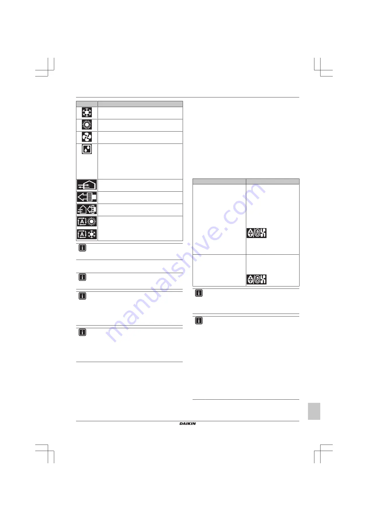
Icon

Operation mode

Cooling.

 In this mode, cooling will be activated as

required by the setpoint, or by Setback operation..

Heating

. In this mode, heating will be activated as

required by the setpoint, or by Setback operation.

Fan Only

. In this mode, air circulates without heating

or cooling.

Dry

. In this mode, the air humidity will be lowered with

a minimal temperature decrease.

The temperature and fan speed are controlled
automatically and cannot be controlled by the
controller.

Dry operation will not function if the room temperature
is too low.

Ventilation

.In this mode, the space gets ventilated,

but not cooled or heated.

Air Clean

. In this mode, the optional air cleaning unit

operates.

Venti Air Clean.

 Combination of ventilation

and air clean operation.

Auto.

 In Auto mode, the indoor unit automatically

switches between heating and cooling mode, as
required by the setpoint.

INFORMATION

Depending  on  the  indoor  unit,  more  or  less  operation
modes are available.

4.2.1

About the operation modes

INFORMATION

If the indoor unit is a cooling-only model, it can only be set
to run in Cooling, Fan only, or Dry operation mode.

INFORMATION

When  operation  modes  are  not  available  in  the  operation
mode menu, it is additionally possible that they are locked.
The  locking  of  operation  modes  occurs  through  the
Madoka  Assistant  app.  For  more  information,  see  the
Madoka  Assistant  app  and 

"14.5.28  Function  lock"  on

page 41

.

INFORMATION

If  the  operation  mode  changeover  of  an  indoor  unit  is
under  centralised  control  ('changeover  under  centralised
control' status icon blinking in the home screen), then it is
NOT possible to change the operation mode of that indoor
unit. 

For 

more 

information, 

see 

"Cooling/Heating

masterhood" on page 32

.

Cooling

If the outdoor air temperature is high, it can take some time until the
indoor room temperature reaches the setpoint temperature.

When the indoor room temperature is low, and the indoor unit is set
to  run  in  Cooling  operation  mode,  the  indoor  unit  can  enter  Defrost
operation  mode  first  (i.e.  Heating  operation),  this  to  prevent  a
decrease  of  the  system's  cooling  capacity  due  to  frost  on  the  heat
exchanger. For more information, see 

"Heating" on page 7

.

The  indoor  unit  can  run  in  Cooling  operation  mode  because  it  is
operating  under  Setback  conditions.  For  more  information,  see

"14.5.18 Setback" on page 39

.

Heating

When  running  in  Heating  operation  mode,  the  system  requires  a
longer  time  to  reach  the  setpoint  temperature  than  when  running  in
Cooling operation mode. To make up for this, it is recommended to
let the system start operation in advance by making use of the timer
function.

The  indoor  unit  can  run  in  Heating  operation  mode  because  it  is
operating  under  Setback  conditions.  For  more  information,  see

"14.5.18 Setback" on page 39

.

To  prevent  cold  drafts  and  a  reduction  of  the  system's  heating
capacity,  the  system  can  run  in  the  following  special  heating
operation modes:

Operation

Description

Defrost

To prevent the loss of heating
capacity due to frost
accumulation in the outdoor unit,
the system will automatically
switch to defrost operation.

During defrost operation, the
indoor unit fan will stop
operation, and the following icon
will appear on the home screen:

The system will resume normal
operation after approximately 6
to 8 minutes.

Hot start (

VRV 

only)

During hot start, the indoor unit
fan will stop operation, and the
following icon will appear on the
home screen:

INFORMATION

When  the  system  is  stopped  while  the  indoor  unit  is
running in Heating operation mode, the fan will continue to
operate for approximately 1 minute, this to get out any heat
remaining in the indoor unit.

INFORMATION

▪ The  lower  the  outdoor  air  temperature,  the  lower  the

heating  capacity.  If  the  system's  heating  capacity  is
insufficient,  it  is  recommended  to  include  another
heating  appliance  into  the  setup  (if  you  use  a
combustion  appliance,  ventilate  the  room  regularly.
Also, do not use the heating appliance in places where
it is exposed to the airflow of the indoor unit).

▪ The  indoor  unit  is  of  the  hot  air  circulation  type.  As  a

result,  after  operation  start,  it  takes  the  indoor  unit
some time to warm up the room.

▪ The  indoor  unit  fan  will  automatically  operate  until  the

indoor  temperature  of  the  system  rises  to  a  certain
level.

▪ When hot air stays under the ceiling and your feet feel

cold, it is recommended to include a circulator into the
setup.

Summary of Contents for BRC1H519K7

Page 1: ...Installer and user reference guide Wired remote controller English Installer and user reference guide Wired remote controller BRC1H519W7 BRC1H519K7 BRC1H519S7...

Page 2: ...13 9 5 2 To open the controller 13 10 Starting up the system 14 10 1 Master and slave controller 14 10 2 To designate a controller as slave 14 11 Remote controller Overview 14 11 1 Buttons 14 11 2 Sta...

Page 3: ...gs and symbols These safety messages are used to attract your attention The meaning of each safety message is described below WARNING Indicates a situation that could result in death or serious injury...

Page 4: ...ocument Target audience Authorised installers end users Documentation set This document is part of a documentation set The complete set consists of Installation and operation manual Installation instr...

Page 5: ...cates that controller s time is not set Self cleaning filter operation Indicates that self cleaning filter operation is active Quick Start Indicates that Quick Start mode is active Sky Air only Test o...

Page 6: ...auses the screen to go blank after a period of inactivity To make the screen light up again press one of the buttons 4 1 2 Main menu From the home screen press to enter the main menu Use and to cycle...

Page 7: ...ation this to prevent a decrease of the system s cooling capacity due to frost on the heat exchanger For more information see Heating on page 7 The indoor unit can run in Cooling operation mode becaus...

Page 8: ...he setpoint in relation to the reference setpoint visually indicated by the marker in the middle of the thermometer It is possible to raise the setpoint three steps of 1 C above and three steps of 1 C...

Page 9: ...Screen Fixed position The indoor unit blows air in 1 of 5 fixed positions Swing The indoor unit alternates between the 5 positions Auto The indoor unit adjusts its airflow direction according to move...

Page 10: ...mode Energy Reclaim Ventilation The outdoor air is supplied to the room after passing through a heat exchanger Bypass The outdoor air is supplied to the room without passing through a heat exchanger...

Page 11: ...ter Replace the indoor unit filter Empty the indoor unit dustbox 6 Troubleshooting 6 1 Overview Troubleshooting When the system is in error consult your dealer To indicate system error the controller...

Page 12: ...a Wiring from the top b Wiring from the left c Wiring from the bottom In case you are routing the wiring from the rear you don t have to remove anything INFORMATION When routing the wiring from the to...

Page 13: ...inch the wiring NOTICE To prevent damage make sure the front of the controller is clicked into the rear casing securely 9 4 2 To close the controller 1 Click the front of the controller into the rear...

Page 14: ...adapter BRP7A5 is part of the system it is not possible to connect and designate a second controller Connecting a second controller when the system already contains the adapter will cause the adapter...

Page 15: ...ndicates that the individual airflow direction setting is enabled Information Indicates that the system has a message to convey To see the message go to the information screen Warning Indicates that a...

Page 16: ...2 Home screen Home screen mode Depending on configuration the controller either has a standard or a detailed home screen While the standard home screen gives you only limited information the detailed...

Page 17: ...icon for each menu reflects the current active setting or mode When operating the controller the menu you navigate through can look different from that represented in this manual The controller only...

Page 18: ...rating under Setback conditions For more information see 14 5 18 Setback on page 39 To prevent cold drafts and a reduction of the system s heating capacity the system can run in the following special...

Page 19: ...set to the setpoint range For more information see 14 5 21 Setpoint range on page 40 Numerical it is only possible to raise or lower the setpoint up down to the maximum minimum setpoint range limits S...

Page 20: ...door units is controlled automatically When the room temperature is higher than the controller s setpoint for Heating operation including Auto operation When the indoor units run in Heating operation...

Page 21: ...ore information see Cooling Heating masterhood on page 32 NOTICE Before starting up the system the unit MUST be energised for at least 6 hours to avoid compressor breakdown during startup INFORMATION...

Page 22: ...nstaller menu 13 1 2 Screen settings To set screen brightness Prerequisite You are in the installer menu 1 Navigate to the screen brightness menu 2 Use and to adjust screen brightness 3 Press to confi...

Page 23: ...st level and settings and values in the second Level Description First level Mode Mode A mode is a group of settable parameters In the field settings tables find available mode numbers in the Mode col...

Page 24: ...NLY set a value for a setting if the value field contains a if the value field does NOT contain a you cannot apply the selected setting to the group SW 00 In the field settings tables find the availab...

Page 25: ...emote sensor set the increase decrease increments 1 C 0 5 C 13 23 00 High air outlet velocity set in case of high ceiling applications h 2 7 m 2 7 m h 3 m 3 m h 3 5 m 01 Airflow direction set in case...

Page 26: ...12 3 0 C 6 7 Home screen 0 Detailed 1 Standard 1 8 Backlight no operation timer 0 5 seconds 1 10 seconds 2 20 seconds 0 9 Status indicator faintness 0 0 OFF 1 1 2 2 3 3 4 5 5 7 6 9 7 11 8 13 9 15 10 1...

Page 27: ...is selected 6 Confirm the address Result You assigned an address to the group of indoor units To assign an address to an individual indoor unit Prerequisite You are in the installer menu 1 Navigate t...

Page 28: ...nstaller menu 1 Navigate to the address settings menu 2 Select I U 3 Define the indoor unit to which you want to assign the address 4 Confirm your selection 5 Define the address 6 Before you confirm t...

Page 29: ...gital input adapter is part of the system the system does not allow for the connection of a slave controller When the digital input adapter is part of the system it is not possible to use the Schedule...

Page 30: ...Key card contact B2 Time Action Contact closed window closed Contact closed key card IN Normal indoor unit operation The unit returns to the previous state before opening the contact Contact open win...

Page 31: ...e the delay timer expires Result The indoor unit stops immediately It is not possible to turn the unit on or off the Setback functionality does not work the delay timer stops counting and the reset ti...

Page 32: ...peration mode The operation mode behaviour of the indoor units is according to the following table If the master Then the slaves is set to Heating Dry or Auto operation mode start running in the same...

Page 33: ...h connection on page 33 2 In the home screen of the app tap the tile of the remote controller of which you want to update the software and follow the instruction from there INFORMATION The Madoka Assi...

Page 34: ...string Result The controller and the mobile device are connected via Bluetooth 8 To update the software follow the instructions from the app To terminate the Bluetooth connection 1 From the home scre...

Page 35: ...equest Result The controller displays the following screen 2 In the app accept the pairing request 3 On the controller accept the pairing request by pressing Result The app is paired with the controll...

Page 36: ...sible to launch a demo version of the app 14 4 2 To launch demo mode Prerequisite You are not in demo mode 1 Go to the main menu 2 Tap Demo mode Result You are in demo mode 14 4 3 To exit demo mode Pr...

Page 37: ...he controller Result During the download the controller displays the following screen Result After the download the controller restarts to implement changes 14 5 3 Notifications Get an overview of act...

Page 38: ...or the system to turn OFF automatically The timer can be enabled or disabled When the timer is enabled it starts running each time the system gets turned ON The timer has a range of 30 180 minutes and...

Page 39: ...tion Dual setpoint There are two temperature setpoints one specifically for Cooling operation and one specifically for Heating operation If this is the case changing the operation mode DOES change the...

Page 40: ...ed automatically making manual fan speed and airflow direction changes impossible 14 5 21 Setpoint range Set a limitation to the temperature setpoint range of both Cooling and Heating operation INFORM...

Page 41: ...ect position For instructions on how to install the digital input adapter see the installation manual of the digital input adapter When the digital input adapter does not function properly external in...

Page 42: ...ng operation and set a timespan for it Reset dustbox maintenance timer When it is time to empty the self cleaning decoration panel s dustbox the app displays a notification in the operation screen Emp...

Page 43: ...ld settings For more information see the installation manual of the optional accessory For details about the specific field settings of each type of indoor unit see the installation manual of the indo...

Page 44: ...n screen set the operation mode to Cooling 5 Go to the Unit settings menu upper right corner of the operation screen Result You are in the Unit settings menu 6 In the Maintenance field tap Test operat...

Page 45: ...isplays the warning screen Status indicator mode Hotel 1 and Hotel 2 Prerequisite The controller displays the home screen and is visible indicating error 2 Press and keep it pressed Result The control...

Page 46: ...3689 1D 2019 05 Status indicator mode Hotel 1 and Hotel 2 Prerequisite The controller displays the home screen and is visible indicating error 2 Press and keep it pressed Result The controller display...

Page 47: ...subset of the latest technical data is available on the regional Daikin website publicly accessible The full set of latest technical data is available on the Daikin Business Portal authentication req...

Page 48: ...ence guide 48 BRC1H519W K S7 Wired remote controller 4P513689 1D 2019 05 Group control master and slave controller 0 1 2 P1 P2 P1 P2 P1 P2 P1 P2 P1 P2 Group control controller digital inputs adapter B...

Page 49: ...17 Technical data Installer and user reference guide 49 BRC1H519W K S7 Wired remote controller 4P513689 1D 2019 05 17 1 3 Controller DIII central control equipment F1 F2 P1 P2 P1 P2 F1 F2...

Page 50: ......

Page 51: ......

Page 52: ...4P513689 1D 2019 05 Copyright 2018 Daikin...

Reviews: