365
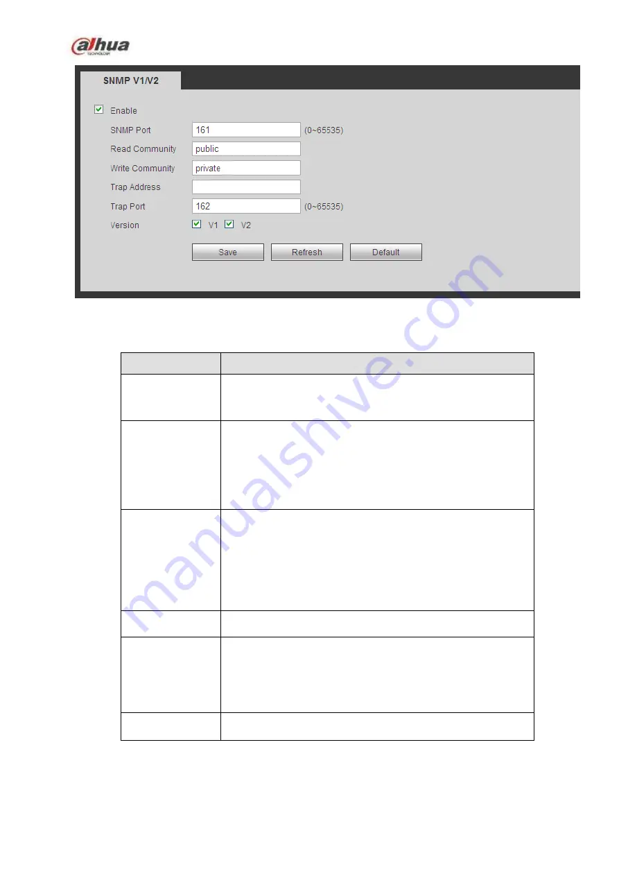
Figure 5-43
Please refer to the following sheet for detailed information.
Parameter
Function
SNMP Port
The listening port of the proxy program of the device. It is a
UDP port not a TCP port. The value ranges from 1 to 65535.
The default value is 161
Read Community It is a string. It is a command between the manage process
and the proxy process. It defined the authentication, access
control and the management relationship between one proxy
and one group of the managers. Please make sure the device
and the proxy are the same.
The read community will read all the objects the SNMP
supported in the specified name. The default setup is public.
Write Community It is a string. It is a command between the manage process
and the proxy process. It defined the authentication, access
control and the management relationship between one proxy
and one group of the managers. Please make sure the device
and the proxy are the same.
The read community will read/write/access all the objects the
SNMP supported in the specified name. The default setup is
write.
Trap address
The destination address of the Trap information from the proxy
program of the device.
Trap port
The destination port of the Trap information from the proxy
program of the device. It is for the gateway device and the
client-end PC in the LAN to exchange the information. It is a
non-protocol connection port. It has no effect on the network
applications. It is a UDP port not TCP port. The value ranges
from 1 to 165535. The default value is 162.
SNMP version
Check V1, system only processes the information of V1.
Check V2, system only processes the information of V2.
5.10.2.11 Multicast
The multicast interface is shown as in Figure 5-44.
Multicast is a transmission mode of data packet. When there is multiple-host to receive the same data
Summary of Contents for NVR1A-4P Series
Page 1: ...Dahua Network Video Recorder User s Manual V 4 3 0 ...
Page 142: ...128 Figure 3 11 3 6 12 NVR42V 8P Series Please refer to Figure 3 12 for connection sample ...
Page 143: ...129 Figure 3 12 ...
Page 157: ...143 Figure 4 15 Step 2 Click device display edit interface See Figure 4 16 ...
Page 220: ...206 Figure 4 93 Figure 4 94 ...
Page 240: ...226 Figure 4 110 Figure 4 111 Figure 4 112 ...
Page 251: ...237 Figure 4 123 Figure 4 124 ...
Page 253: ...239 Figure 4 126 Click draw button to draw the zone See Figure 4 127 ...
Page 257: ...243 Figure 4 130 Click Draw button to draw a zone See Figure 4 131 Figure 4 131 ...
Page 262: ...248 Figure 4 136 Click draw button to draw the zone See Figure 4 137 ...
Page 275: ...261 Figure 4 148 Figure 4 149 ...
Page 276: ...262 Figure 4 150 Figure 4 151 ...
Page 387: ...373 Figure 5 60 Figure 5 61 ...
Page 388: ...374 Figure 5 62 Figure 5 63 ...
Page 412: ...398 Figure 5 96 Figure 5 97 ...


