117
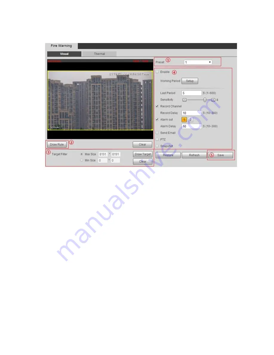
Figure 6-53
1. Select
“Preset” and the camera will quickly move to the corresponding location of the preset.
2. Click
“Draw Rule” to draw monitoring area in the monitoring image.
3. Select max or min size, click
“Draw target” and drag any angle of the filtering box to zoom in or out
to adjust the filtering box to proper size.
Note:
It will trigger alarm only when the detected fire is between two filtering boxes.
In the state of drawing, select
“Max Size” or “Min Size”, click “Clear” to delete corresponding
rectangular box.
4. Enable fire warning and set parameters, please refer to sheet 6-30 for more details.
5. Click
“Save” to make config valid.
Thermal
Step 1
Enter thermal fire warning setting interface.
Different devices have different modes to enter the interface, please refer to the actual interface, and
please select one of the following modes to enter the interface.
Select
“Setup > Smart Thermal > Fire Warning > Thermal” and the system will display the interface
of
“Thermal”.
Select
“Setup > Event > Fire Warning” and the system will display the interface of “Fire Warning”.
Summary of Contents for DH-TPC-PT8320A
Page 1: ...i Multi spectral Thermal Camera Web3 0 Operation Manual Version 1 0 0 ...
Page 8: ...3 Figure 1 4 ...
Page 17: ...12 Figure 2 8 ...
Page 54: ...49 Figure 5 2 ...
Page 98: ...93 Figure 6 33 ...
Page 146: ...141 Figure 6 74 Figure 6 75 ...
Page 169: ...164 Figure 6 102 ...


