DGS-3700-12/DGS-3700-12G Series Layer 2 Gigabit Ethernet Switch User Manual
126
MIP
This setting controls the creation of MIPs.
None
– Means that no MIPs will be created. This is the default value.
Auto
– MIPs are created when the next lower active MD-level on the port is reached or there are
no lower active MD levels.
Explicit
– MIPs are created when the next lower active MD-level on the port is reached.
SenderID TLV
Used to define the TLV data types of the maintenance domain. The user can choose between
None
,
Chassis, Manage
or
Chassis Manage
.
To create a new entry enter the appropriate information and click
Add
. To configure the settings enter the appropriate
information and click
Apply
.
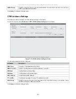
CFM Loopback Settings
This window is used to configure the CFM Loopback settings on the Switch.
To view this window, click
L2 Features
> CFM > CFM Loopback Settings
as shown below:
Figure 3 - 83 CFM Loopback Settings window
The following parameters can be configured:
Parameter Description
MEP Name
(Max:32
characters)
The name of the Maintenance End Point.
MEP ID (1-8191)
The ID for the Maintenance End Point between
1
and
8191
.
MD (Max:22
characters)
The Maintenance Domain Name.
MA (Max:22
characters)
The Maintenance Association Name.
MAC Address
The destination MAC address.
LBMs Number (1-
65535)
The number of LBMs to be sent the default value is 4.
LBM Payload
Length (0-1500)
The payload length of the LBM to be sent, the default value is O.
LBM Payload
Pattern
(Max:1500
characters)
The arbitary amount of data to be included in a Data TLV, along with the indication of whether
the Data TLV is to be included.


