MB95310L/370L Series
Document Number: 002-07519 Rev. *A
Page 42 of 80
(Continued)
*5: Applicable to the following pins: P00 to P07, P10, P11, P13 to P16, P20 to P22, P40 to P43, P50 to P53, P60 to P67, P90 to P95,
PA0 to PA3, PB0 to PB7, PC0 to PC7, PE0 to PE7, PG0
■
Use under recommended operating conditions.
■
Use with DC voltage (current).
■
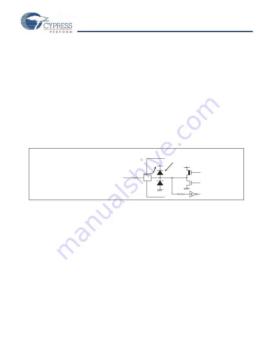
The HV (High Voltage) signal is an input signal exceeding the V
CC
voltage. Always connect a limiting resistor between the HV
(High Voltage) signal and the microcontroller before applying the HV (High Voltage) signal.
■
The value of the limiting resistance should be set so that when the HV (High Voltage) signal is applied the input current to the
microcontroller pin does not exceed rated values, either instantaneously or for prolonged periods.
■
When the microcontroller drive current is low, such as in low power consumption modes, the HV (High Voltage) input potential
may pass through the protective diode to increase the potential of the V
CC
pin, and thus affects other devices.
■
If the HV (High Voltage) signal is input when the microcontroller power supply is off (not fixed at 0 V), since power is supplied
from the pins, incomplete operations may be executed.
■
If the HV (High Voltage) input is input after power-on, since power is supplied from the pins, the voltage of power supply may
not be sufficient to enable a power-on reset.
■
Do not leave the HV (High Voltage) input pin unconnected.
■
Example of a recommended circuit
WARNING:
Semiconductor devices can be permanently damaged by application of stress (voltage, current, temperature, etc.) in
excess of absolute maximum ratings. Do not exceed these ratings.
HV(High Voltage) input (0 V to 16 V)
Protective diode
V
CC
N-ch
P-ch
R
Limiting
resistor
• Input/Output equivalent circuit


