CYUSB3KIT-001 EZ-USB FX3 Development Kit Guide, Doc. #: 001-70237 Rev. *C
23
Getting Started
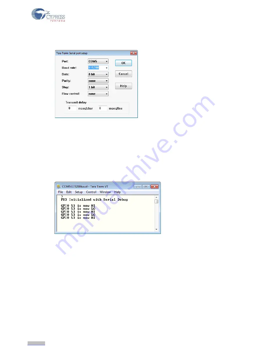
3. Choose
Setup > Serial Port
and adjust the baud rate to 115,200. Then press
OK
(
Figure 2-21
).
Figure 2-21. Select 115,200 baud rate
4. Load and run the code as in the first example. To recap: If the USB Control Panel is not already
running, choose
CY Tools>Control Center
, press the board RESET button, choose
Program>FX3>RAM
, navigate to the .img file in your Workspace and load the program. You
should see a screen similar to that shown in
Figure 2-22
. Every time you press the push button
an interrupt-driven function displays the GPIO[53] pin state. This simple application does not de-
bounce the button, so you may see several messages per button push. If you have not
connected a push button to GPIO[53] then these debug messages can be observed by
connecting this GPIO to ground using a jumper wire.
Figure 2-22. FX3 Sending Debug Messages
FX3 firmware sends serial debug messages using the
CyU3PDebugPrint
function, for example
for the sign-on message,
CyU3PDebugPrint (4, “\r\n FX3 Initialized with Serial
Debug\r\n\r\n”)
;.
The first parameter sets a debug message priority. Your program can set a priority threshold to
enable some messages and disable others.
Downloaded from
Downloaded from
Downloaded from
Downloaded from
Downloaded from
Downloaded from
Downloaded from
Downloaded from
Downloaded from
Downloaded from
Downloaded from
Downloaded from
Downloaded from
Downloaded from
Downloaded from
Downloaded from
Downloaded from
Downloaded from
Downloaded from
Downloaded from
Downloaded from
Downloaded from
Downloaded from


