Culligan Iron-Cleer Installation And Operation Instructions With Parts List Download Page 40

 36

  Culligan

®

 Iron-Cleer

R

 Water Filters

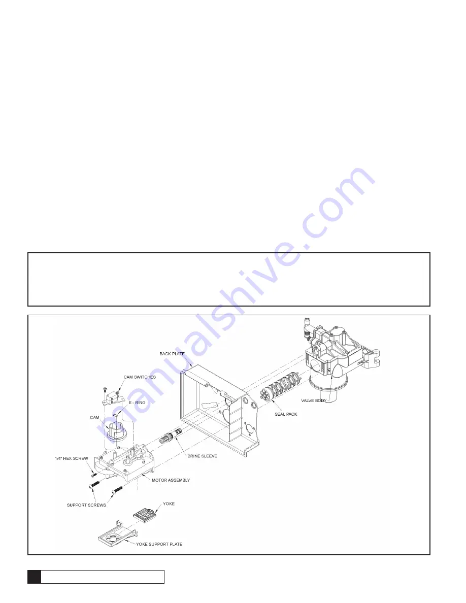
Drive Motor Assembly

1.  Remove the drive motor cam switches by removing the one screw holding the switches to the motor.
2.  Remove the E-ring holding the drive motor cam to the camshaft with a flat tip screwdriver.
3.  Lift the cam off the shaft.
4.  Remove the screw above the brine sleeve assembly.
5.  Loosen the two screws holding the yoke support plate and the motor to the control valve.
6.  Remove the yoke support plate and yoke by gently pulling them down.
7.  Fully remove the two screws holding the motor to the control. The motor will pull away from the control and the backplate will 

hang on the valve body.

This procedure can be followed in the reverse order to reassemble the motor to the control. When reassembling the scotch yoke, 

the yoke must slide into the yoke support plate prior to pushing the assembly up into the piston end and follower. Figure 19 shows 

proper assembly of the yoke into the support plate.

Note:

  The seal pack may need to be repositioned in order for the follower to be inserted into the yoke, using the motor and 

backplate to push the seal pack fully into the valve is helpful in aligning the yoke. Make sure that the follower is in the follower slot 

on the yoke, and that the end of the piston rod is held in the end of the yoke.

Note:

   When attaching the yoke support plate be certain to push up on the plate until the two mounting screws bottom in the  

U-shaped channels of the support plate.

Figure 18

Summary of Contents for Iron-Cleer

Page 1: ...Cat No 01020478 Rev A2 11 26 07 DCO 010173 Installation and Operation Instructions with Parts List Culligan Iron Cleer Water Filters Models from 2007 2007 Culligan International Company ...

Page 2: ...ts but we believe that product knowledge is best obtained by consulting with your Culligan dealer Untrained individuals who use this manual assume the risk of any resulting property damage or personal injury Culligan International Inc 9399 West Higgins Road Suite 1100 Rosemont IL 60018 847 430 2800 Warning Prior to servicing equipment disconnect power supply to prevent electrical shock Warning If ...

Page 3: ...7 Table of Contents Page Introduction 1 Specifications 2 Preparation 3 Installation 8 Settings 16 Circuit Board 17 Programming 18 Manual Cycling 23 Service Check 25 Start Up 27 Recommended Preventative Maintenance 28 Troubleshooting Guide 29 Operation Maintenance Service 35 Wiring Diagram 39 Parts List 40 ...

Page 4: ... Culligan Iron Cleer Water Filters ...

Page 5: ...t but does not present any hazard Example Caution Caution is used when failure to follow directions could result in damage to equipment or property Example Warning Warning is used to indicate a hazard which could cause injury or death if ignored Example Serial Numbers The control assembly serial number is top center on the rear of the timer plate The media tank serial number is on the top of the s...

Page 6: ... 12 x 52 tanks Filter Media Type 1 0 cu ft birm 1 5 cu ft birm Underbedding G 50 35 lbs 35 lbs Cullsan U 25 lbs 25 lbs Capacity1 1400 gallons 2000 gallons Freeboard2 21 18 Max Clear Water Soluble Iron 10 ppm 10 ppm Max Hydrogen Sulfide 5 0 ppm 5 0 ppm Minimum Alkalinity 100 ppm 100 ppm pH for Iron Removal 7 0 8 5 7 0 8 5 pH for Hydrogen Sulfide Removal 6 5 7 5 6 5 7 5 Service Flow Pressure Drop Cl...

Page 7: ...rs standard or locking groove Gauge Assembly PN 00304450 or equivalent Silicone lubricant PN 00471507 or equivalent Do Not Use Petroleum based Lubricants Lubricating swabs PN 00591610 carton of 12 Thread sealing tape A bucket preferably light colored Towels Special Tools Torch solder and flux for sweat copper connections Use only lead free solder and flux for all sweat solder connections as requir...

Page 8: ... Oxidized iron particles are trapped by the filter bed as the water passes through Filtered water enters the lower distributor and travels up the distributor tube to the outlet port on the filter valve Step 2 Aeration Operation Air Recharge Cycle When energized the air pump sends air through the solenoid valve into one end of the shuttle valve Once air pressure in the shuttle valve is greater than...

Page 9: ...lter bed Raw water enters the filter control valve through the inlet port and is directed down the distributor tube and out the lower distributor at the bottom of the tank flowing upward through the multimedia filter bed toward the top of the tank into the control valve Water is then directed through a specific flow restrictor and out the drain port to be discharged to drain Step 4 Filter Tank Ope...

Page 10: ...nfluent water must be 7 0 8 5 A pH level of 7 0 8 5 is optimal for iron reduction Iron This system is rated for a maximum of 10 ppm of ferrous clear water and or ferric red water iron Consult the factory if iron bacteria is present Hydrogen Sulfide Often referred to as rotten egg odor hydrogen sulfide will be reduced significantly on water supplies containing less than 5 ppm Consult the manufactur...

Page 11: ...ht Outdoor installation is not recommended and voids the warranty If installing in an outside location you must take the steps necessary to assure the filter installation plumbing wiring etc are as well protected from the elements sunlight rain wind heat cold contamination vandalism etc as when installed indoors ___ Check Valve On applications where there is a non filtered demand for water such as...

Page 12: ...This will allow the media to become soaked while completing the rest of the installation 6 Screw the inlet strainer into the tank Mount The Control Valve See figure 2 for a visual on mounting the control valve to the tank Assemble the o rings located in the parts pack to the tank adapter The valve adapter o ring sits on the first step on the adapter See figure 3 Lubricate only the top o ring on th...

Page 13: ...bow from the filter control valve 3 Remove the rubber backwash flow control washer and discard it 4 Install the thin black flow control washer into the filter control valve with the molded numbers facing the control valve Install the plastic flow control spacer Install the drain elbow and retaining clip Retainer Clip Install Thin Flow Control Washer Remove This Flow Control Washer Drain Elbow Inst...

Page 14: ...er replaces the coupling on the outlet side of the control The meter body fits in the same space as the coupling between the control valve and the bypass Make sure that the arrow on the flow meter is pointing in the direction of flow Figure 5 Caution Close the inlet supply line and relieve system pressure before cutting into the plumbing Flooding could result Warning DO NOT remove the Cul Flo Valv...

Page 15: ... 6b Electrical Connections The power cord needs to be connected to the plug in transformer wire orientation is not critical Figure 6c shows the cord attachment to the transformer Connect wire harness to 24 VAC terminals on transformer About 1 1 4 A screwdriver shank may be used in the slot as a lever for extra turning force if needed Figure 6b Figure 6a Note Observe all state and local electrical ...

Page 16: ...ain line not be connected together Water flowing to drain from the solenoid vent line is a means of troubleshooting the solenoid will normally expect very little moisture unless an internal seal fails from within the valve body Run the drain lines to a suitable waste outlet such as a laundry tub floor drain or stand pipe and in accordance with local plumbing codes To prevent back siphoning of drai...

Page 17: ... 9 3 Locate the large tube provided and mark it 4 3 8 from the end Insert it into the white disperser and aeration head until it contacts the stop molded into the aeration head Approximately 4 3 8 of the tube will be in the white disperser when properly seated Use the mark to verify it is inserted deep enough See figure 9 4 Tighten the screw on the white disperser to secure the two tubes as shown ...

Page 18: ... 13 Note Tighten the plastic nuts by hand only 10 Run 1 4 tubing from the solenoid valve exhaust port and 3 8 tubing from the aeration head drain connection to an atmospheric drain separate from the filter drain See figure 14 11 The outlet of the aeration tank is then connected to the inlet of the filter tank 1 diameter pipe is recommended 12 Remove the front cover from the unit so the time delay ...

Page 19: ...n Normal Operation Bypass Operation Treated Water Exits Supply Water Enters Supply Water Exits Supply Water Enters Shut Off Mode No Water Exits Supply Water is Shut Off From The House and The Valve Diagnostic Mode Supply Water Exits Supply Water Enters ...

Page 20: ... for the eduction and rinsing of salt or other regenerant chemical The pause step duration is 2 minutes Rapid Rinse Step Rapid rinse settles and compacts the media after backwashing and flushes any residual particulate matter from the bottom of the filter bed before returning the filter to service Rapid rinse is set at the factory at 10 minutes It may be extended if desired Refer to the Programmin...

Page 21: ...per left side of the board Next to the meter connection is a connection marked BATT which is for the optional battery back up All terminals are clearly marked to ease installation Figure 16 Build A 3107 1 2 3 4 5 6 7 8 R T DE IM SO FI TCB E M 12 24 75 1 SL FA ON DIP SWITCHES 1 2 3 4 5 6 7 8 ON OPTIONAL BATTERY CONNECTION FLOW METER CONNECTION BACKSIDE OF CIRCUIT BOARD WIRE HARNESS CONNECTION MICRO...

Page 22: ... soft ener On The unit shall function as a filter The default time programmed for cycle 2 shall be 2 minutes 4 TCB Time Clock Back up Disabled Enabled Off The time clock backup option is not enabled On Allows the user to enable the time clock function of the control as a backup regeneration initiation option This feature is used as a back up to a primary device such as a flow meter 5 E M English M...

Page 23: ...Menu Accessed from service mode by holding the key for 5 seconds Delay Immediate Toggle Delay or Immediate Delay Locks in a regen signal after a 3 hour or more power outage regen can be set to go immediate or delay until the tor Only accessible from service mode time of day display by pressing and holding for 5 seconds not in programming menu Lock Unlock Toggle Lock Unlock Unlock Lock or unlock ac...

Page 24: ...o the next programming step Pressing Regen will move back to the minutes adjust Time of Regeneration This setting is used to program the time at which a regeneration is to occur in the delay mode or in immediate mode with time clock backup on The display will first show tor for two seconds After tor is shown the display will then show the default of 2 00 AM or the current programmed time of regene...

Page 25: ...tage greater than 3 hours It applies only when dip 2 is set for delay The display will show the REG icon and dEL or Id depending on the last saved setting default to dEL if EEPROM has no saved value Toggle between dEL and Id with the or key If set to dEL then after power outage greater than 3 hours the regen icon will light and the regeneration will begin when the timer reaches the next programmed...

Page 26: ...appear as normal but their values will not be able to be changed Note The hidden menu can always be accessed and settings within the hidden menu can always be changed even if locked The display will show Loc or UnL depending on the last saved setting default to UnL if EEPROM has no saved value Toggle between Loc and UnL with the or keys Pressing the Status key will save the setting exit the Hidden...

Page 27: ...e motor will move the control to Backwash position Press the key to cycle to the next position and remain there until the cycle times out or the control is manually indexed Continue to press the key until the control returns to the service Home position In order to step through the cycles again repeat at step 3 Note if the key is pressed at any time the control will move back to the first item in ...

Page 28: ... key A 2 will appear in the display along with the cycle time remaining The control is in the Settline cycle 4 Press key A 3 will appear in the display along with the cycle time remaining The control is now in the FAST RINSE cycle 5 Press the key An H will appear in the display The unit is in the HOME position The REG enunciator is no longer blinking 6 Press the status key Time of Day appears in t...

Page 29: ...generations Life of the Unit 0 to 9 999 Counter is to be updated after completion of valid regeneration cycle cycle 3 times out automatically To be saved in EEPROM before the control is powered down during a power outage Once the statistics menu is entered the information shown for each display is outlined below Regen key is always ignored in statistics mode Can enter directly into diagnostics mod...

Page 30: ...play will show totL for two seconds and then display the total number of valid regenerations for the life of the unit Statistical Function Timeout If no key activity occurs for a period of 600 seconds 10 minutes while in statistics functions mode the mode will time out and return to the time of day display Pressing the Status key at any time will return he unit back to the time display ...

Page 31: ...When water flows to drain open the inlet valve fully Watch the drain discharge for media particles If media particles appear reduce the flow Increase the flow again when media particles no longer appear in the discharge When the unit is filled with water return the timer to the service position 7 Start up is complete Caution The media must be soaked for at least 12 hours before start up see prepar...

Page 32: ...ently depending on the raw water quality Test Water Feed Product Hardness Iron Hydrogen Sulfide Chlorine TDS Other Comments Bypass Valve Bypass in Service or Bypass Condition of bypass valve Operation OK Control Valve Condition of Seal Pack Condition of Solenoid Valve Condition of Motor Condition of Flow Control Condition of Switches Condition of Check Valve Condition of Shuttle Valve Condition of...

Page 33: ... manufacturer D Inadequate aeration 1 Loss of air through inlet check valve 1a Check installation position of check valve Consult Installation and Operation Manual for proper position 1b Check for foreign material in seat of check valve clean or replace as required 2 Loss of air through air leak 2 Check aeration tank assembly and air recharge line and fittings for any air leaks and repair Note soa...

Page 34: ...ce check valve 3 Worn or faulty check valve 3 Replace check valve Air spurting from filtered water fixtures A Reduced pressure in distribution system 1 Service flow demand is greater than water supply available from well pump system 1 Repair or replace well pump system 2 Water flow is restricted by supply piping and or water treatment equipment 2a Eliminate restrictions in supply piping to water t...

Page 35: ...on piping system 1 Low pH condition of the raw water supply 1 A Cullneu filter may be required to elevate the pH consult factory 2 In rare occasions highly aerated water in combination with a specific water supply can create a slightly corrosive condition 2 Install a polyphosphate cartridge filter after the Iron Cleer Filter System to protect the distribution piping Compressor doesn t run 1 Compre...

Page 36: ...motor The control will attempt to start the motor 3 times for 70 seconds each time with a 60 second off period between each attempt Press and hold STATUS key for 10 seconds Motor Failure to Stop unex pected switch changes If the control detects changes in the Cam inputs when the motor is not supposed to be turning Press and hold STATUS key for 10 seconds Incorrect Cycle Position switch changes out...

Page 37: ...eration Reset and reprogram the board The board repeatedly defaults resets or gains time Look at the power supply or source Most of these issues are caused by the power source so called dirty power having noise interference or incorrect voltage This could be erratic fluctuations caused by other heavy power draws poor wiring low voltage wiring running along high voltage having active electrical sto...

Page 38: ...splay to show 11 Press Status Key Key Display to show 12 and motor to run for 15 seconds Press Key Key Display to show 13 and turns on Chlo rinator output for 15 seconds IF chlorina tor is connected Press Key Regen Key Display to show 14 Press Regen Key Home Switch Display to show H when Home switch closed Close Home Switch Display to Blank when open Open Home Switch Position Switch Display to sho...

Page 39: ...ower to the unit before servicing Bypass the unit and relieve system pressure before attempting to repair Caution Grip all connections to the circuit board by the connecting terminals for assembly and disassembly Failure to do so could result in damage to the wire leads or connecting terminals Caution Do not touch any surfaces of the circuit board Electrical static discharges may cause damage to t...

Page 40: ...he valve body This procedure can be followed in the reverse order to reassemble the motor to the control When reassembling the scotch yoke the yoke must slide into the yoke support plate prior to pushing the assembly up into the piston end and follower Figure 19 shows proper assembly of the yoke into the support plate Note The seal pack may need to be repositioned in order for the follower to be i...

Page 41: ... the drive motor set aside firmly pull the eductor sleeve assembly from the valve body 2 Lightly lubricate the o rings of the replacement sleeve assembly with silicone grease 3 Reverse the procedure for reassembly Note Use only silicone grease petroleum based lubricants will cause the degradation of the rubber components Note The eductor sleeve assemblies are unique to the softener filter and Supe...

Page 42: ...ng the relay check to see that it is set properly See the setting instructions To replace the relay remove timer cover grasp the relay firmly and pull it straight out of its socket When replacing the relay line up the key on the relay with the slot in the socket Air Compressor The compressor may need replacement if it a fails to deliver air to the media tank or b makes excessive noise To test the ...

Page 43: ...Plus Control Yellow Red Brown Brown Circuit Board Gearmotor Black Black Power Cord Motor Position Switch Top Motor Home Switch Bottom Compressor Solenoid Valve Black Black Green Black White Black White Green Ground 2 1 8 7 6 5 4 3 Wiring Diagram 39 ...

Page 44: ...ulligan Iron CleerR Water Filters 36 23 35 29 28 27 34 26 30 64 33 23 38 22 21 20 31 24 18 66 32 2 5 9 11 15 16 10 8 4 3 1 17 12 43 44 42 40 41 Control Valve Parts List 24 5 9 11 15 16 8 10 8 4 3 1 2 17 12 ...

Page 45: ...r Eductor Port 10 pk 17 P0448687 Screw 25 ea pk 20 01014787 Medallist Power Cord 21 01006498 Plug Dome 22 P1000372 Cord Grip Fitting 25 pk 23 01019708 Medallist Enclosure Kit includes cover back plate hinge pin label and wire clip 24 P1001258 Sleeve Eductor Filter 10 pk 26 01014179 Drive Motor Kit 24v 60hz 27 P0318452 Screw 25 ea pk 28 01012933 Yoke 29 01012926 Bracket 30 P1013031 Cam 10 pk 31 P10...

Page 46: ...or 1 control Filter Aeration tank for 3 4 control 01014456 Replacement tank 12 x 52 empty w o manifold Filter tank for 1 control A2365028 Replacement tank 12 x 52 empty w o manifold Aeration tank for 1 control 1 P1009099 O ring outlet manifold 1 control 50 pk 2 01014539 Outlet manifold 10 x 54 1 control 01014540 Outlet manifold 12 x 52 1 control 01011195 Strainer 01017724 10 Tank Base 01017752 Scr...

Page 47: ...p 1 22 Air Filter 1 23 Housing 1 24 Gasket Front Cover 1 25 Front Cover 1 26 Screw Stator 2 28 Retainer 1 30 Pipe Plug 1 Item No Description Qty 1 Screw Head 4 2 Head 1 3 O Ring Head 1 4 Screw Exhaust Valve Flapper 1 5 Valve Keep Strip 1 6 Exhaust Valve Flapper 1 7 O Ring Valve Flapper 1 8 Valve Plate 1 9 O Ring Piston Sleeve 1 11 Piston Sleeve 1 12 Screw Ramped Intake Valve Flapper 1 13 Intake Va...

Page 48: ... Kit 6 01018743 Solenoid Valve Kit 7 01018744 Disperser and Bleed Tube Kit 8 01018745 Seal Kit 9 01018161 Pickup Tube 10 01018746 Plumbing Connector Kit 1 Male NPT 11 P1018748 Plumbing Connector Kit 1 Brass Sweat 12 01018921 Tool Kit Solenoid Valve Duckbill Check valve replacement 44 Culligan Iron CleerR Water Filters Aeration Parts List 1 2 3 4 5 6 7 8 9 10 11 10 11 8 8 5 ...

Reviews: