background image

CU-ERT Operator’s Manual_ver 1.10 


54

Printing Data From the Paramedic CU-ERT 

 
a.


Connect the printer UART cable to the Paramedic CU-ERT’s UART port. 

b.


If it is desired to operate the printer using power from the AC adapter, connect the AC adapter 
power cord to the power mains and the AC adapter output to the printer power port. If it is 
desired to run the printer using power from the Paramedic CU-ERT, do not connect the AC adapter. 

c.


Do not connect any connector (AED or ECG monitoring pads connector) to the ECG-DEFIB port of 
the Paramedic CU-ERT. 

d.


If it is desired to print data contained in the SmartMedia card, insert the SmartMedia card into its 
port in the Paramedic CU-ERT, otherwise, do not insert the SmartMedia card and the data in the 
internal flash memory will be printed. 

e.


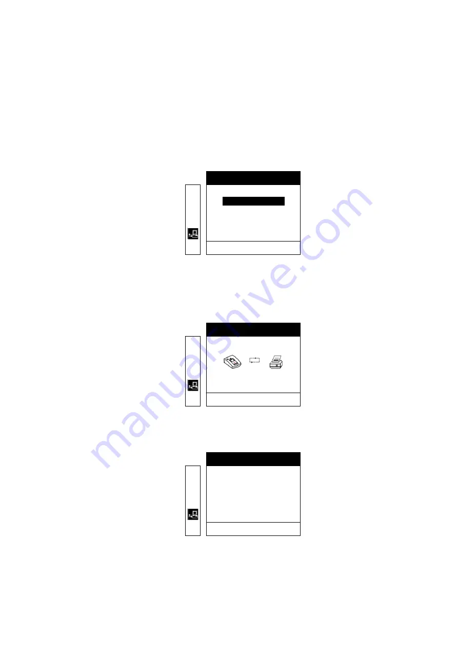
Turn the Paramedic CU-ERT ON. Activate the menu. Go to COMMUNICATION, highlight PRINT 
then press the MENU button. The following screen will be displayed 


L

‡

#

©

'

PRINT

RETURN

'

PRINT ALL

PRINT SEGMENT

•

•


Pressing the MENU button will print all ECG and Event data stored in the active data memory storage 
(internal data flash memory if no SmartMedia card is present, SmartMedia card if it is present in its 
port) 


The following figure will be displayed during printing 


L

‡

#

©

'

PRINT ALL

PRESS THE MENU KEY TO RETURN

'


f.


If it is desired to print only a segment of the stored ECG data, highlight PRINT SEGMENT, then 
press the MENU button. The following screen will be displayed 


L

‡

#

©

'

PRINT

PRESS THE MENU KEY TO RETURN

'

POWER ON                                   00:00:00

PADS ON                                       00:00:00

ANALYZING                                  00:00:05
SHOCK ADVISED                         00:00:09

ARMED                                         00:00:18

1/5                                        

X


Summary of Contents for CU-ERT

Page 1: ...CU s Emergency Responder 1 Training Kit Operator s Manual CU Medical Systems Inc Paramedic Series AED CU ERT English 1 10 ...

Page 2: ...CU ERT Operator s Manual_ver 1 10 2 Operator s Manual Semi automated External Defibrillator Trainer CU ERT ver 1 10 ...

Page 3: ... upgraded to comply with the American Heart Association 2005 Guidelines for Cardiopulmonary Resuscitation CPR and Emergency Cardiovascular Care ECC 2005 CPR Guidelines are applied to the ERT after software version 1 10 Specifications and information contained in this Operator s Manual are subject to change without prior notice ...

Page 4: ...erface 19 4 7 1 LCD Display 19 4 7 2 Power Switch and SHOCK Button 22 4 7 3 Menu Buttons 22 4 7 4 Infrared Remote Controller 23 4 7 5 Light indicators 25 4 7 6 Speaker and beeper 25 4 8 Menu Operation 26 5 Device Preparation Set Up 36 5 1 Unpacking 36 5 2 Power Connection 36 5 3 Rescue Setup 36 6 Operation 36 6 1 Operation Scenario Groups 36 6 2 Paramedic CU ERT Operation 36 6 3 Scenarios 37 6 3 1...

Page 5: ...2 SmartMedia Card 44 8 2 2 1 Installation of a SmartMedia Card 44 8 2 2 2 Removal of a SmartMedia Card 44 8 2 2 3 Reviewing Data Using A SmartMedia Card 45 8 3 Data Transfer To Personal Computer 46 8 3 1 IrDA 46 8 3 2 UART Port 48 8 4 Printing Using a Stand alone Serial Printer 50 9 Maintenance 56 9 1 Cleaning the Paramedic CU ERT 58 9 2 Troubleshooting Guide 59 9 3 Safety Considerations 59 APPEND...

Page 6: ...vicing of the device There are no user serviceable parts in this device z You should ensure that all power sources are properly installed or connected before using this device z You should operate this device in accordance with the instructions specified in this manual This device is intended for use during trainings such as CPR training Basic Cardiac Life Support BCLS training or Advanced Cardiac...

Page 7: ...e device is sold z The warranty period of this device is within two years after the date of purchase z When the device malfunctions during the warranty period it will be repaired free of charge at our service centers z When you submit the device for maintenance please specify the details as listed below The name of model product serial number date of purchase name of sales representative informati...

Page 8: ...tted for maintenance immediately When any abnormalities are found in the device or when a danger to bodily harm exists the device has to be repaired fast and adequately by authorized personnel When the need for maintenance arises z Please contact CU Medical Systems Inc or its authorized representatives immediately Prepare a summary of the problems Also include the name of model product serial numb...

Page 9: ...5 Fax 82 33 478 5729 email address admin cu911 com Service Request and Technical Support Customer Service Team CU Medical Systems Inc Dongwha Medical Instrument Complex 1647 1 DongHwa Ri Munmak Eup Wonju si Gangwon do Republic of Korea Tel 82 33 747 7657 Fax 82 33 747 7659 email address service cu911 com Our website http www cu911 com EU Authorized Respresentative of CU Medical System Inc Branch O...

Page 10: ...to emphasize the safety practices that must be observed and followed during the operation of the Paramedic CU ERT The operator must follow the instructions in all the Warnings Cautions and Notices found throughout this Operator s Manual In the event that the product is damaged due to misuse or negligence by a user the manufacturer or the authorized representatives shall not be responsible for the ...

Page 11: ...re directly exposed to sunlight Do not store the device in areas with highly fluctuating temperatures Do not store the device near heating equipment Do not store the device in areas where there is high vibration in excess of Category 10 of MIL STD 810E Do not operate or store the device in environments with high concentration of flammable gas or anesthetics Do not operate or store the device in ar...

Page 12: ...ore and operate the device in locations that are exposed to chemicals explosive gas and solvents z Keep the device away from dusty environments z There are no user serviceable parts inside the Paramedic CU ERT Only authorized service personnel should open the device for repairs z During recharging when the device is connected and disconnected from the mains power connector hold the plug and not th...

Page 13: ... z Check the case of the device for any apparent damage z Check the ports defibrillator lead port UART port adapter power port to see that they are tightly in place z Check the accessories especially the defibrillation pads to see that they are in good condition and that they have not yet reached their expiration dates Do not immerse any part of the Paramedic CU ERT in fluids Do not let any fluid ...

Page 14: ...is to be used in conjunction with the resuscitation mannequin from CU Medical Systems Inc It has a standard infrared remote control accessory which renders it operable by an instructor from a distance 3 2 Intended Use The Paramedic CU ERT is intended for use during Advanced Cardiac Life Support training Basic Life Support training or any other physician approved trainings that deal with the operat...

Page 15: ...CU ERT Operator s Manual_ver 1 10 15 4 Basic Orientation 4 1 Controls Indicators and Ports ...

Page 16: ...d shock Delivers the simulated shock when pressed while the backlight is flashing MENU keys Control special functions such as device setup and data management and review 4 3 Indicator Lamps POWER Indicates that the source of power is the AC adapter BATTERY This indicator is not used no function in the Paramedic CU ERT ERROR Indicates that a system error occurred If error lamp is on contact the ser...

Page 17: ... its accessories External Disposable Battery Pack Used to power the trainer Resuscitation Mannequin Used to simulate connection with a patient IrDA COM Port Serial Adapter Used to transmit data to a personal computer 4 5 Input Output Ports ECG DEFIB port Used to connect the defibrillator pad assembly to the device Also used to connect the custom made ECG MONITORING CABLE AND CONNECTOR ASSEMBLY to ...

Page 18: ... not touch the patient NO SHOCK ADVISED Indicates that the patient has a non shockable ECG rhythm CHARGING Indicates that the Paramedic CU ERT is charging its capacitor for a subsequent shock delivery CHARGING COMPLETE Indicates that the Paramedic CU ERT has finished charging its capacitor for a subsequent shock delivery PRESS THE SHOCK BUTTON Indicates that the user has to press the SHOCK button ...

Page 19: ...ly the same user interface as the Paramedic CU ERT except for the infrared remote controller that is not available on the Paramedic CU ERT 4 7 1 LCD Display Splash Screen When the power is turned ON the following splash screen is displayed on the LCD of the Paramedic CU ERT Splash Screen ...

Page 20: ...ice can still deliver ten 150J shocks When this is displayed the battery pack should be replaced Do not wait for the battery pack to be drained below the level where the Paramedic CU ERT could not operate anymore Battery Status Icon When the AC DC Adapter is on Use the device is powered by an AC adapter or a Car cigar lighter jack Prompt Displays the action that needs to be done by the operator El...

Page 21: ...ained below the level where the Paramedic CU ERT could not operate anymore Battery Status Icon When the AC DC Adapter is on Use the device is powered by an AC adapter or a Car cigar lighter jack Rhythm Scenario Indicator Indicates the rhythm being displayed on the screen or the rescue scenario being run Text Prompt the commands issued by the device that guides the user throughout the rescue proces...

Page 22: ...wer switch and the SHOCK buttons respectively 4 7 3 Menu Buttons The menu is activated and navigated using the Menu Buttons The UP Button scrolls the highlighter up during Menu operation The DOWN Button scrolls the highlighter down during Menu operation The MENU Button when pressed selects the option highlighted by the highlighter bar ...

Page 23: ...U ERT Operator s Manual_ver 1 10 23 4 7 4 Infrared Remote Controller This enables an instructor to control the Paramedic CU ERT from a distance Infrared Remote Controller Actual Shape Key Button Markings ...

Page 24: ...0 bpm loop when the key is pressed repeatedly VF Simulates the acquisition and display of a ventricular fibrillation ECG rhythm VT 180 240 Simulates the acquisition and display of a ventricular tachycardia ECG rhythm The rate is cycled through the 1800 240 bpm loop when the key is pressed repeatedly ASYS Simulates the acquisition and display of an asystole ECG rhythm CS1 Customer defined rescue sc...

Page 25: ...Paramedic CU ERT Error indicates that an error has occurred Power Switch Button Backlight when ON indicates that the Paramedic CU ERT is ON SHOCK Button Switch Backlight flashes when the SHOCK Button needs to be pressed to simulate the prompt for a SHOCK delivery 4 7 6 Speaker and beeper Speaker plays back the appropriate recorded prompts during operation Beeper beeps during charging completion si...

Page 26: ...umber and total elapsed time of device usage b the number of shocks delivered c the number and total elapsed time of trainings conducted using the device d the number and total elapsed time of the different tests daily weekly monthly and manual tests To go to device history press the following keys Turn ON the device Press MENU key three times The following screens will be displayed A 17 Sep 2003 ...

Page 27: ...0 12 B L DEVICE INFORMATION L DEVICE HISTORY BATTERY HISTORY RETURN C L DEVICE INFORMATION L RETURN DEVICE HISTORY BATTERY HISTORY D L DEVICE INFORMATION RETURN L DEVICE HISTORY BATTERY HISTORY E L BATTERY HISTORY L USAGE TIME 43500 MIN GOOD STATUS PRESS THE MENU KEY TO RETURN USAGE TIME Total time that the internal battery pack is used as power supply of the Paramedic CU ERT This time is counted ...

Page 28: ...dumped on the internal dump resistance of the Paramedic CU ERT The charge in the defibrillating capacitor is automatically dumped when the SHOCK button is not pressed within 15 seconds after the prompt to press the SHOCK button is given Shock X Indicates the time when the X th shock is delivered by the Paramedic CU ERT Analyzing Indicates the time when the Paramedic CU ERT is analyzing the ECG of ...

Page 29: ...CE HISTORY BATTERY HISTORY RETURN C L REVIEW INCIDENT USAGE REVIEW ECG REVIEW VOICE REVIEW RETURN D L REVIEW INCIDENT USAGE REVIEW ECG REVIEW VOICE REVIEW RETURN E L USAGE REVIEW RETURN ELAPSED TIME 7 Sep 2003 00 03 22 3 TOTAL SHOCKS 22 00 DETAILED REVIEW F L USAGE REVIEW POWER ON PRESS THE MENU KEY TO RETURN PADS ON ANALYZING SHOCK ADVISED ARMED 1 2 00 00 00 00 00 02 00 00 05 00 00 08 00 00 17 X ...

Page 30: ...ely Scroll the data by pushing the UP or DOWN arrow button To go to ECG REVIEW press ON MENU DOWN MENU DOWN MENU The following screens will be displayed A 17 Sep 2003 ATTACH PADS 00 00 12 B L DEVICE INFORMATION L DEVICE HISTORY BATTERY HISTORY RETURN C L REVIEW INCIDENT USAGE REVIEW ECG REVIEW VOICE REVIEW RETURN D L REVIEW INCIDENT USAGE REVIEW ECG REVIEW VOICE REVIEW RETURN E L REVIEW INCIDENT U...

Page 31: ... displayed A 17 Sep 2003 ATTACH PADS 00 00 12 B L DEVICE INFORMATION L DEVICE HISTORY BATTERY HISTORY RETURN C L REVIEW INCIDENT USAGE REVIEW ECG REVIEW VOICE REVIEW RETURN D L REVIEW INCIDENT USAGE REVIEW ECG REVIEW VOICE REVIEW RETURN E L REVIEW INCIDENT USAGE REVIEW ECG REVIEW VOICE REVIEW RETURN F L REVIEW INCIDENT USAGE REVIEW ECG REVIEW VOICE REVIEW RETURN L VOICE REVIEW PRESS THE MENU KEY T...

Page 32: ...DMINISTRATION RETURN F L GENERAL RETURN 03 09 09 00 15 ON UART DATE TIME VOICE REC COM PORT G L GENERAL RETURN 03 ON UART DATE TIME VOICE REC 09 09 00 15 COM PORT The variable parameters are highlighted one by one by pressing the MENU button while the variable is highlighted For example when DATE is highlighted the day month or year can be highlighted by pressing the MENU button When a variable pa...

Page 33: ...ions ECG Gain 5 10 20 AUTO mm mV You can select one among the 4 options The following screens are displayed A 17 Sep 2003 ATTACH PADS 00 00 12 B L DEVICE INFORMATION L DEVICE HISTORY BATTERY HISTORY RETURN C L REVIEW INCIDENT USAGE REVIEW ECG REVIEW VOICE REVIEW RETURN D L DEVICE SETUP RETURN GENERAL ADMINISTRATION E L DEVICE SETUP GENERAL ADMINISTRATION RETURN F L DEVICE SETUP GENERAL ADMINISTRAT...

Page 34: ...ECG data press ON MENU DOWN DOWN DOWN MENU DOWN DOWN MENU The following screens will be displayed A 17 Sep 2003 ATTACH PADS 00 00 12 B L DEVICE INFORMATION L DEVICE HISTORY BATTERY HISTORY RETURN C L REVIEW INCIDENT USAGE REVIEW ECG REVIEW VOICE REVIEW RETURN D L DEVICE SETUP RETURN GENERAL ADMINISTRATION E L COMMUNICATION RETURN DATA RECEPTION DATA TRANSMISSION PRINT F L COMMUNICATION RETURN DATA...

Page 35: ...ion highlight the RETURN option or icon then press the MENU button You will then be taken to the next higher level in the system If you are in the highest sublevel highlighting the RETURN icon and then pressing the MENU button will take you back to RESCUE mode and the Paramedic CU ERT will prompt you to ATTACH PADS ...

Page 36: ... refers to the simulation wherein the chosen ECG rhythm is continuously acquired by the Paramedic CU ERT The ECG rhythm does not change throughout the operation unless changed by the user b Customer Scenario this refers to the scenario that is programmed by the user This is not available for this version of the Paramedic CU ERT c Training Scenario this refers to the rescue scenarios that are progr...

Page 37: ...repeatedly d The name of the ECG rhythm and the beat rate will be shown on the LCD before the said ECG rhythm is displayed on the LCD screen and while the same ECG rhythm is running 6 3 4 VF a This is initiated by pressing the VF key on the Remote Controller b A Ventricular Fibrillation ECG rhythm will be simulated and fed to the Paramedic CU ERT c The name of the ECG rhythm and the beat rate will...

Page 38: ...hm converted to non shockable Normal Sinus Rhythm d The name of the Training Scenario will be shown on the LCD before the said scenario is displayed on the LCD screen and while the scenario is running 6 3 9 S3 Training Scenario 3 a This is initiated by pressing the S3 key on the Remote Controller b 80 bpm Normal Sinus Rhythm all throughout c The name of the Training Scenario will be shown on the L...

Page 39: ... rhythm c The following will be simulated i Shockable rhythm ii 1st shock iii CPR countdown 30 2 15 2 iv Rhythm converted to non shockable Normal Sinus Rhythm d The name of the Training Scenario will be shown on the LCD before the said scenario is displayed on the LCD screen and while the scenario is running 6 3 13 S7 Training Scenario 7 a This is initiated by pressing the S7 key on the Remote Con...

Page 40: ... all throughout no conversion to Normal Sinus Rhythm c The name of the Training Scenario will be shown on the LCD before the said scenario is displayed on the LCD screen and while the scenario is running 6 3 16 S10 Training Scenario 10 a This is initiated by pressing the S10 key on the Remote Controller b Ventricular Fibrillation with one shock required for conversion followed by a low battery con...

Page 41: ... The battery pack is connected to the Paramedic CU ERT through the AC DC adapter port and the UART Port The connector of the battery pack is embedded with connectors that match the AC DC and UART Port connectors To connect the external battery pack do the following a Plug in the connector of the external battery pack to the UART port and the AC DC Adapter port simultaneously The UART port and AC D...

Page 42: ...a 100V to 240V AC b 50 60 Hz line frequency The AC DC Adapter Power cord Connecting the AC DC Adapter a connect the power cord to the power mains outlet and to the AC DC adapter b connect the output of the AC DC Adapter to the AC DC Adapter port on the Paramedic CU ERT DC Output Power Cord Connector Receptacle Mains Plug Plug for AC DC Adapter ...

Page 43: ...f the Paramedic CU ERT Audio signal data can not be recorded here It is nonvolatile thus the stored data is not erased when the device is turned OFF The Internal Data Flash Memory has a capacity of 12 hours of ECG and Event data recording The whole memory location is erased at the beginning of a rescue operation thus data stored from a previous rescue operation is overwritten To keep previously re...

Page 44: ... SmartMedia Card is clean and dry b Turn the Paramedic CU ERT OFF c Load the SmartMedia Card with the metallic strip facing down and the notched end going in first Push the card all the way in until the card hits a stop The SmartMedia Card is ready to record data when the Paramedic CU ERT is turned on for use d When the device is turned on with the SmartMedia Card inserted the SmartMedia card data...

Page 45: ...ressing the UP S or DOWN T key When the SmartMedia Card is inserted to the Paramedic CU ERT for recording of rescue data all the data present in the SmartMedia Card will be overwritten with data from the current rescue operation The previous data will no longer be retrievable To preserve data through a series of rescue operations the data must be transferred to a personal computer before using the...

Page 46: ... of the Paramedic CU ERT Insert the SmartMedia Card if the data to be transferred is in the SmartMedia Card See the illustrations on the CU Expert User s Manual The Paramedic CU ERT must be set to communicate through its IrDA port by setting the COM PORT to IrDA as outlined in the GENERAL DEVICE SETUP of the section on MENU OPERATION Transmit the data from the Paramedic CU ERT through the followin...

Page 47: ...tion icon will also stop moving the arrow tips Attempts to establish a connection will be stopped if no connection is made in 1 minute This icon is also shown if data transfer is cancelled due to interference e The progress of the data transmission will be tracked by a progress bar in the LCD display of the Paramedic CU ERT f The order of device activation can also be reversed It is possible to se...

Page 48: ... Activate the MENU by pressing the MENU button Go to COMMUNICATION DATA TRANSMISSION The following screen should be displayed L COMMUNICATION RETURN DATA RECEPTION DATA TRANSMISSION PRINT e Push the MENU button The data transmission screen will be displayed L DATA TRANSMISSION PRESS THE MENU KEY TO RETURN When the Paramedic CU ERT is communicating the Communication icon will show moving arrow tips...

Page 49: ...ta and then set the CU Expert to receive data h When the data transmission is completed the CU Expert ECG Data Management Software will prompt the user about the completion of the transmission The completion of the data transmission is also shown by a full progress bar in the LCD display of the Paramedic CU ERT i When the transmission is finished the Paramedic CU ERT may be turned OFF It is also p...

Page 50: ...nd alone serial printer Stand alone Serial Printer The optional stand alone printer is a serial printer configured to receive data using RS232 protocol The stand alone printer set that comes with the Paramedic CU ERT optional is composed of the printer UART cable AC adapter AC power cable ECG printer paper These are shown in the figure below ...

Page 51: ... this mode the printer is powered by the Paramedic CU ERT through the UART port b Connect the printer to the Paramedic CU ERT and at the same time connect the DC output of the AC adapter to the printer power port In this mode the AC Adapter is supplying power to the printer The printer is not drawing power off the Paramedic CU ERT The printer power port is shown in the next figure ...

Page 52: ... paper When the button is pressed and then released the printer paper advances one line When the button is pressed continuously the printer paper advances continuously until the button is released Power Indicator Lamp this indicator lamp is ON when the printer is ON Data Transmission Indicator Lamp this indicator lamp turns ON when the device is receiving data Error Indicator this indicator lamp i...

Page 53: ...ed pull the paper compartment lid upward This is shown in the following figure 2 Place a roll of printer paper as shown in the following figure The printing surface must face the paper cutter of the printer 3 Close down the lid of the printing paper compartment Allow around inch of printer paper to go past the paper cutter to ensure that the paper will feed properly during printing ...

Page 54: ...rwise do not insert the SmartMedia card and the data in the internal flash memory will be printed e Turn the Paramedic CU ERT ON Activate the menu Go to COMMUNICATION highlight PRINT then press the MENU button The following screen will be displayed L PRINT RETURN PRINT ALL PRINT SEGMENT Pressing the MENU button will print all ECG and Event data stored in the active data memory storage internal dat...

Page 55: ...g the DOWN button As the DOWN button is pressed the Events included in the segment to be printed are highlighted The ending point will be the last highlighted event After choosing the range to be printed the screen display will look like this L PRINT SEGMENT PRESS THE MENU KEY TO RETURN 1 5 X ARMED 00 00 18 POWER ON 00 00 00 PADS ON ANALYZING SHOCK ADVISED 00 00 00 00 00 05 00 00 09 To print the c...

Page 56: ...e to the pollution of the environment Maintenance Activities Frequency Activity Actions to be Taken Check supplies accessories and spare parts for damage and expiration If any supplies have expired replace them immediately Check the case of the Paramedic CU ERT and the accessories for any sign of apparent damage If there is any apparent damage to the case of the device consult the manufacturer Mon...

Page 57: ...e ID ______________ Date Scheduled Frequency Paramedic CU ERT Clean no signs of damage free of excessive wear Supplies Available 2 sets of pads undamaged sealed within expiration date supplementary supplies razor scissors gloves gauze Remarks Problems Corrective Actions Inspected by Signature of operator doing the inspection ...

Page 58: ...mixture 30 ml bleach liter of water Ammonia based cleaners Hydrogen peroxide Do not immerse any part of the Paramedic CU ERT in fluids Do not let any fluid enter the case of the device Do not spill liquids on the case of the device Do not use strong acetone based cleaners in cleaning the device Do not use abrasive materials in cleaning the unit especially on the LCD display and the infrared filter...

Page 59: ...efibrillation pads on the bare chest of the patient Follow the graphic direction provided at the back of each defibrillation pad ATTACH PADS The defibrillation pad assembly is not connected to the ECG DEFIB port of the Paramedic CU ERT Attach the connector of the defibrillation pad assembly to the ECG DEFIB port of the Paramedic CU ERT The defibrillation pads are not attached well to the patient s...

Page 60: ...ce text prompts guide the user through the rescue protocol All the user interfaces are supported in local language for easy use and access Data Storage Management Internal flash memory 12 hours of event and ECG recording SmartMedia Card 32M 48 hours of event and ECG recording or 1 hour recording if voice recording is enabled Review of the patient s ECG incident details and device information Data ...

Page 61: ...nual_ver 1 10 61 CU Medical Systems Inc Address 534 Dusan VentureDigm 126 1 Pyeongchon dongan Anyang si Gyeonggi do Republic of Korea TEL 82 31 478 5725 FAX 82 31 478 5729 HOMEPAGE http www cu911 com E mail admin cu911 com ...

Reviews: