Operation Manual
www.critical-environment.com
Rev. C | 2022.02
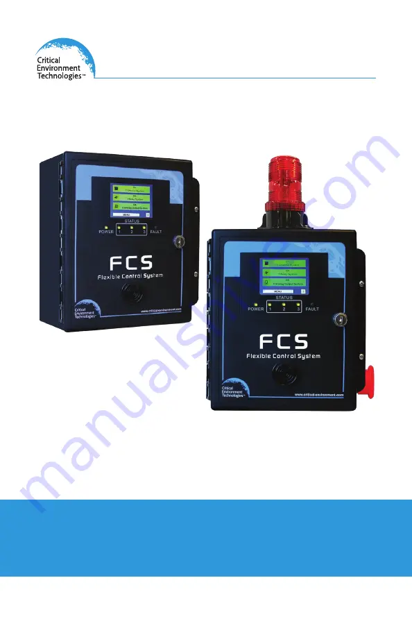
FCS
Flexible Control System Controllers
Page 1: ...Operation Manual www critical environment com Rev C 2022 02 FCSFlexible Control System Controllers...
Page 2: ...e installation information including the following topics please refer to the FCS Installation Manual Location of System Installation Standard Enclosure Mounting Components Wiring Power Supply Wiring...
Page 3: ...the Menu with Passcodes 15 4 3 Home Screen Display 17 4 3 1 Summary Display Factory Default 17 4 3 2 Channel Scrolling Display 23 4 3 3 Calibrating the Display to Improve Response 23 4 4 Silencing the...
Page 4: ...Logic and Delays 48 9 4 Assign Priority Levels Logic Conditions to Analog Outputs 48 9 5 Analog Input Calibration requires a 4 20 mA source 52 9 6 Analog Output Calibration requires a 4 20 mA meter 5...
Page 5: ...s of Using Priorities 72 12 4 1 Gas Concentration Priority Example 73 12 4 2 Time of Day Priority Example 74 12 4 3 Calibration Expired Priority Example 75 12 4 4 Title 24 Occupied Priority Example 77...
Page 6: ...ical Environment Technologies Canada Inc warrants the products we manufacture excluding sensors battery packs batteries pumps and filters to be free from defects in materials and workmanship for a per...
Page 7: ...Unit 145 7391 Vantage Way Delta BC V4G 1M3 You must include your Returned Merchandise Authorization RMA number address telephone number contact name shipping billing information and a description of t...
Page 8: ...l wiring be within properly grounded earth or safety conduit 1 6 Revisions This manual was written and published by CETCI The manufacturer makes no warranty or representation expressed or implied incl...
Page 9: ...ault conditions extensive menu system with password protection enhanced logic control priorities zoning capabilities a USB port for firmware upgrades data logging and a door mounted audible alarm The...
Page 10: ...service department for technical support 2 3 Technical Specifications GAS TYPE No internal gas sensors MECHANICAL Enclosure ABS Polycarbonate rated UL94 HB Copper coated interior to reduce RF interfe...
Page 11: ...ring VAC line voltage three conductor Line Neutral Ground shielded minimum 18 AWG stranded within conduit LAN Modbus RTU RS 485 4 conductor 16 AWG stranded shielded WAN output to BAS 4 conductor 16 AW...
Page 12: ...any interference received including interference that may cause undesired operation 2 4 Maximum Features by Model FCS 4 FCS 8 FCS 32 FCS 128 Gas Channels 4 8 32 128 Analog Inputs 4 8 32 60 Analog Outp...
Page 13: ...P Public Spaces 4 20 mA CO2 CO CH2 O Refrigerants C3 H8 TVOCs Particulates Various Infrared Solid State Catalytic PID CGAS D Digital Modbus CO2 NH3 CO NO2 CLO2 Cl2 C3 H4 C2 H4 O CH2 H2 H2 S HCl HCN NO...
Page 14: ...ATION 4 1 Navigating the Menu Structure The FCS has a 1 4 VGA full colour resistive touch LCD display A certain amount of pressure is required to engage the buttons as is a certain length of time To i...
Page 15: ...n If you are going through more channels or relays or priorities on the same screen the system will autosave when you press the or to proceed or return to the next channel relay priority number If you...
Page 16: ...lts Relay Override Set Clear Relay for specific length of time 3022 Configure Configure Channel Hardware Enable Disable Channels Set Channel Communication Type analog digital Set Channel ID Assign Sen...
Page 17: ...nnel 4 3 1 Summary Display Factory Default The Summary view of the home screen display shows three bars on the display The first is the Channel Status bar the second is the Relay Status bar and the th...
Page 18: ...At least one channel is in Fault condition exclusive of other possible states occurring at the same time To view more details about the channels press on the icon on the left side of the Channel Statu...
Page 19: ...con here to exit the details screen The details screen allows you to view the alarm level setpoints priorities it is assigned to the type of fault when it was last calibrated its Modbus ID and a descr...
Page 20: ...ys labeled RL1 RL2 RL3 and RL4 Strobe horns and the internal audible buzzer are also counted as relays The FCS may also have remote relays RLY 4 and or RLY 8 connected to it The Relay Status Bar on th...
Page 21: ...ther than OK normal operation Or press here to see the list of only the active relays Or press here to see the list of only the silenced horns strobes Press here to see the list of all the relays and...
Page 22: ...t will display the three most important statuses in order from left to right The bar will also change colour depending on the severity of the status The status Fault is displayed in red and shows the...
Page 23: ...or entering the number in the field To save the configuration press ENTER Press HOME to return to the home screen 4 3 3 Recalibrating the Display to Improve Response The FCS has a 1 4 VGA full colour...
Page 24: ...rmined amount of time You will also be able to see how many alarms have been previously silenced and how many are currently sounding You can silence all or none of the alarms When the Silence is pushe...
Page 25: ...nded for AUDIBLE devices horns integral buzzer etc directly connected to the FCS or the relays including the RLY 4 or RLY 8 but any relay can be configured as silenceable 5 TESTING FUNCTIONS In the Te...
Page 26: ...sing the keypad to enter the number 5 1 Test Audible Buzzer NOTE Before testing the audible alarm warn people in the vicinity of where the sound will be heard so it does not cause unnecessary distress...
Page 27: ...ople so unnecessary distress or response is not caused In Test menu passcode 1 press on Test Relays Enter the relay number you want to test and enter the length of time you want to test the relay for...
Page 28: ...t settings listed below There may be some differences in the default settings depending on application If changes to the default settings are desired the settings can be changed in the field as indica...
Page 29: ...nalog Input Calibration 4 20 mA 0 20 mA Analog Output Calibration 4 20 mA 0 20 mA STEL TWA Display Channel Alarm Global Alarm Off Disabled Disabled On Off Disable Enable Disable Enable The Basic menu...
Page 30: ...S 8 FCS 32 FCS 128 4 max 4 max 20 max 20 max RDM Mode Choose from these display modes Line Scroll ALL channels in the system will be displayed and the four line display will scroll up by one line at a...
Page 31: ...ection of channels see the FCS Operation Manual 6 4 Data Logging Settings The FCS comes standard with an SD card installed and data logging enabled You are able to change the logging interval disable...
Page 32: ...n the Data Logger menu 6 4 3 How to Delete Data Log Files A log file is created every 24 hours at midnight local time and every time the FCS is powered up restarted Over time the files take up space a...
Page 33: ...ypad For each channel you can enter Enabled or disabled If a channel is disabled it will show on the normal display with a d at the end of the line unless that line has been removed from showing on th...
Page 34: ...Save if in doubt 7 2 Set Channel Name UOM and Gas Range Values This setting enables you to give each channel a name specify the units of measure number of decimal places and enter a value for the Zero...
Page 35: ...r PPM To change the unit of measure press on the desired number letter or symbol button repeatedly until the desired character appears Press Save to save the edits made to the Name or Units For each c...
Page 36: ...ired Priority Logic for more information Press Menu and enter passcode 3022 to enter the Config Channel menu and select Channel Calibration Date If you want to review the current settings for each cha...
Page 37: ...e hysteresis is set for 10 ppm the alarm will not turn off until the gas is below 90 ppm This prevents the alarm from chattering on and off repetitively if the gas fluctuates just above and just below...
Page 38: ...VAC each and can be used to control remote alarms strobes exhaust fan starters make up air fan contactors or signaling other equipment like fire panels or alarm systems etc NOTE The door mounted buzz...
Page 39: ...ellow fields to use the keypad to change the values To enable or disable the channel latching failsafe mode or silencing press on the corresponding button green indicates the feature is enabled and wh...
Page 40: ...ormation refer to Section 8 4 How to Clear a Latched Relay Silencing Not Silencing If you would like to silence the channel of the internal audible buzzer a terminal connected strobe or horn or a remo...
Page 41: ...d increase above the alarm setpoint and then drop a few moments later when the car leaves The ON Delay tells the system to wait a specified length of time before taking the gas level seriously and to...
Page 42: ...f you are going through more relays on the same screen the system will auto save when you press the or to proceed or return to the next relay number If you press Home or Back the change will not be sa...
Page 43: ...number NOTE A latched relay cannot be overridden The override status along with the amount of time left for it to be in that state can be viewed by pressing on the Relay Status Bar and using the or bu...
Page 44: ...e relays the strobe horn and or internal audible Press Menu and enter passcode 2012 to enter the Set Alarm menu and select Relay Disable Use the and buttons or enter the specific relay number by press...
Page 45: ...t device such as CETCI s 4 20 mA analog transmitters that may be connected to the internal AI Option s and or the LNK AI peripheral device s and associated analog input channels Press Menu and enter p...
Page 46: ...nels Each LNK AI peripheral device has four 4 20 mA analog input channels Enable Disable Select Enable or Disable for the chosen channel Press Save to save the changes 9 2 Enable Disable Analog Output...
Page 47: ...position or 2 if the AO board is installed in the bottom position For an LNK AO peripheral device or Modbus VFD choose a number from 75 to 99 For the last output channel choose 229 to indicate that t...
Page 48: ...nnel is set to Step Mode Only be applied to LOW MID and HIGH alarm triggered events Range from 0 to 30 minutes Default factory setting is 0 minutes ie no delay 9 4 Assign Priority Levels Logic Conditi...
Page 49: ...and use the keypad to enter the specific number Use the and buttons or press on the yellow fields to use the keypad to change the settings A Output Choose the analog output for which you want to confi...
Page 50: ...mA output percentage output for VFDs Priority Add change or remove the priority levels this analog output will look at Fault Output this value if any of the channels in the priorities selected go into...
Page 51: ...els in the selected priorities has a time of day priority engaged Normal Output this value if the channels in the selected priorities are reporting everything is normal but you want the analog output...
Page 52: ...value if all priorities are reporting everything is normal but you want the analog output to remain on Press SAVE to save the changes NOTE The step functionality does not cause the fan to ramp up it...
Page 53: ...FCS thinks the current is this value will change as you change the A D values or the 4 20 mA source A D 4 mA While applying 4 mA change the number until the mA value is 4 mA A D 20 mA While applying 2...
Page 54: ...are desired follow the same steps using the preferred mA value instead of 4 mA and 20 mA 10 STEL AND TWA SETTINGS STEL Short term Exposure Limit The STEL is the acceptable average exposure over a shor...
Page 55: ...t Channel STEL TWA If you want to review the current STEL TWA settings for each channel press the or buttons Or use press the yellow field to use the keypad and enter the specific channel number Use t...
Page 56: ...24 functionality to work properly the Title 24 Faults flag and the Calib Expired Faults flag must all be En enabled Press on Dis disable or En enable for each of the STEL TWA and or IDLH alarms Press...
Page 57: ...ity Stop bits 1 Data bits 8 NOTE The FCS has been designed to operate with these parameters and any changes made could affect its ability to work as intended If these values are changed CETCI will not...
Page 58: ...s includes the Building Management System if used 11 1 1 Set Modbus ID Remote Baud Rate and Local Baud Rate For an FCS Controller with Modbus WAN output press Menu and enter passcode 1001 to enter the...
Page 59: ...ect baud rate is displayed The FCS factory default baud rate is 76 800 Press ENTER to save Power the FCS off and then on again 11 2 Modbus Holding Registers The FCS Controller is configured to communi...
Page 60: ...0 Relay 1 0 or 1 2 1 Relay 2 0 or 1 3 2 Relay 3 0 or 1 4 3 Relay 4 0 or 1 5 4 Strobe connected to remote strobe horn terminal 0 or 1 6 5 Audible internal 0 or 1 7 6 Horn connected to remote strobe hor...
Page 61: ...o its scaler value is 100 An ambient NO2 gas measurement of 0 4 ppm would be represented in the register as 0 4 x 100 40 NOTE The STEL and TWA values are not valid if the configuration does not enable...
Page 62: ...ls and up to a maximum of 8 for the FCS 8 models 30 006 30 006 Channel 2 STEL 30 007 30 007 Channel 2 TWA 30 008 30 008 Channel 2 Alarms 30 009 30 009 Channel 3 Reading 30 010 30 010 Channel 3 STEL 30...
Page 63: ...Priority_ 7 status 31 009 Priority_ 8 status 31 010 Priority_ 9 status etc 11 2 4 Analog Output Registers Analog output registers are the present value being output to the analog output channels and a...
Page 64: ...d of list mark 229 12 LOGIC AND PRIORITY SETTINGS AND CONFIGURATIONS 12 1 Assign Priority Levels to Channels This setting enables you to assign priority levels to each channel One channel can be assig...
Page 65: ...priority can activate the relay Using this AND and OR logic the priorities can be combined in multiple ways increasing the number of possible configurable relay combinations To enter the Config Channe...
Page 66: ...gure Priority Logic You can choose to configure the priority logic for gas concentration settings time of day settings expired calibration date Title 24 occupied time settings and selected channels to...
Page 67: ...Remote Enable Choose On to allow remote disable and Off to disable remote enable If the gas detection system is not connected to a remote interface such as a DDC BAS FIRE PANEL etc the flag should be...
Page 68: ...figuration This would be useful if you were required to monitor the STEL TWA throughout a work shift Use the and buttons to ensure Time of Day is showing Priority Choose a priority number that will be...
Page 69: ...or s should be calibrated If when the time expires the FCS will trip that priority as a fault If the fault occurs the senor should be calibrated as soon as possible The system will remain operational...
Page 70: ...was Calibrated and Calibration Expired Priority refer to the previous Section 12 3 3 Title 24 is a California Building Standards Code that governs the design and construction of all building occupanci...
Page 71: ...need to go to Channel Logic and assign the priority to each applicable channel Refer to Section 12 1 Assign Priority Levels to Channels For an example of using the Title 24 Occupied Priority refer to...
Page 72: ...and strobe that is connected to the RDM will only be triggered by the channels being displayed on that RDM Once the priority has been created you need to go to Channel Logic and assign the priority t...
Page 73: ...Relay Logic For Relay 1 Set trigger level T1 to 1 the 1 indicates P1 Set Alarm to L for Low alarm Set Logic to OR Set trigger level T2 to 1 the 1 indicates P2 Set Alarm to M for Mid alarm Set Logic to...
Page 74: ...channels goes into Mid Alarm the exhaust fan will be turned on 12 4 2 Time of Day Priority Example SCENARIO During the time that people arrive for work and park in the underground parking lot you wan...
Page 75: ...rity Example SCENARIO Channels 1 2 and 3 have sensors that should be calibrated every year and channels 4 and 5 have sensors that should be calibrated every 6 months You would like the system to keep...
Page 76: ...c For Priority 4 Choose Calibration Expired Use the button to enter 12 Press SAVE For Priority 5 Choose Calibration Expired Use the button to enter 6 Press SAVE For more information on Priority Logic...
Page 77: ...ained at 25 ppm or less at all times 5 The ventilation rate shall be at least 0 15 cfm ft2 when the garage is scheduled to be occupied 6 System shall maintain the garage at negative or neutral pressur...
Page 78: ...nfig Channel Menu Priority Logic refer to Section 12 3 3 NOTE The priority numbers and relay numbers used in the examples are arbitrarily chosen In real life it is common to start with the first unuse...
Page 79: ...acility with an ice rink and a restaurant you want the RDM in the restaurant to only display the Carbon dioxide CO2 gas readings from the sensor in the CO2 tank room and the RDM mounted at the second...
Page 80: ...remote strobe and the internal buzzer will be triggered Each RDM requires its own single priority logic The system knows which RDM is which based on its Modbus ID If you set more than one priority for...
Page 81: ...es no assembly and virtually no maintenance It is important to ensure that water and or dust is not somehow entering the enclosure and physically damaging the circuit board or internal components 16 T...
Page 82: ...on it is recommended to do a restart of the FCS Push and hold the button on the FCS circuit board until the buzzer chirps approximately a count of 12 let go and the FCS will do a restart NOTE Restarti...
Page 83: ...2022 All rights reserved Data subject to change without notice 83 Rev C 2022 02 FCS Operation Manual NOTES...
Page 84: ...Technologies Canada Inc All rights reserved Data in this publication may change without notice Unit 145 7391 Vantage Way Delta BC V4G 1M3 Canada Tel 1 604 940 8741 Toll Free 1 877 940 8741 www critic...