06
SENSOR INSTALLATION
The Sensor sits in a balance line, tank or trough to monitor the project’s water level. A ball
float inside the Sensor lowers as the water level drops, in turn connecting a light beam
between two LED lights in the top of the Sensor. These lights complete an electrical circuit
and the Control Box opens the Solenoid to add water to the project.
As water is added to the project, the water level rises and the ball float is pushed to
the top of the Sensor. As the ball intersects the light beam at the top of the Sensor,
the Control Box recognises the full water level. Instead of stopping the flow immediately,
the TIME DELAY MODE then overfills the project for a set period as dictated by the
particular setting.
The Water Witch Sensor is available in standard lengths of 5m, 20m, 30m, 40m, 50m
and 60m. Special order sensors can be manufactured up to 250m long.
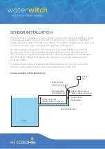
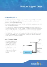
Sensor installed in first balance line
Balance line to be
300mm below water level
Cable gland to
adjust sensor height
Sensor set to
desired level
50mm balance line
Control
Box
Balance line to extend
300mm above water level
DO NOT GLUE
50mm END CAP
POOL


