


Safety
Information
Product
Information
Mechanical
Installation
Electrical
Installation
Getting
Started
Menu 0
Running
the motor
Optimisation
Macros
Advanced
Parameters
Technical
Data
Diagnostics
UL Listing
Information
98
Unidrive User Guide
www.controltechniques.com Issue Number: 9
8.2 Current limits
The default setting for the current limit parameters are 150% x motor
rated current for open loop and closed loop vector modes and 175%* x
motor rated current for servo mode. *150% for Unidrive size 5.
There are three parameters which control the current limits:
•
Pr
4.05
Motoring current limit
: power flowing from the drive to the
motor
•
Pr
4.06
Regen current limit
: power flowing from the motor to the
drive
•
Pr
4.07
Symmetrical current limit
: current limit for both motoring and
regen operation
The lowest of either the motoring and regen current limit or the
symmetrical current limit applies.
The maximum setting of these parameters depends on the ratio of motor
rated current to drive rated current and the power factor.
The drive can be oversized to permit a higher current limit setting to
provide higher accelerating torque as required up to a maximum of
400%.
Please note that too high a setting of these parameters can cause
permanent damage to a servo motor by demagnetising the rotor.
The maximum current limits (I
MAX
%) available for each mode of
operation, are calculated from the following equations.
Pr 3.10 / 3.11 / 3.12 Speed loop gains
The speed loop gains control the response of the speed loop to a change in speed demand.
The default values give satisfactory performance for most applications however for optimal performance in dynamic applications the values may
require tuning for the specific motor.
Inappropriate values entered in these parameters can cause the control system to become unstable.
The proportional gain (Pr
3.10
) responds proportionally to the difference between the demanded value and the actual value (the error).
The integral gain (Pr
3.11
) responds proportionally to the accumulation of the error. It is used to eliminate steady state error and under dynamic
conditions provide stiffness to the system.
The derivative gain (Pr
3.12
) is proportional to the rate of change of the error. It improves the stability of the system under transient conditions.
The speed loop gains can be tuned by either:
1. Using an oscilloscope and the method described below
2. The gain calculator wizard in Unisoft version 3.43, which requires the following:
• motor inertia
• load inertia (reflected through the gear box if used)
• stiffness / compliance angle (user defined deflection of the motor shaft when full torque is applied)
• drive rated current
• motor nameplate details
Tuning the speed loop gains using an oscilloscope
Connect the oscilloscope to analog output 1 to monitor the speed
feedback.
Give the drive a step change in speed reference and monitor the
response of the drive on the oscilloscope.
The proportional gain should be set up initially - the value should be
increased up to the point where the speed overshoots and then reduced
slightly.
The integral term should then be increased up to the point where the
speed becomes unstable and then reduced slightly.
If a derivative gain is required the value should be increased up to the
point where the system response becomes unstable and then reduced
slightly.
It may now be possible to increase the proportional gain to a higher
value and the process should be repeated until the system response
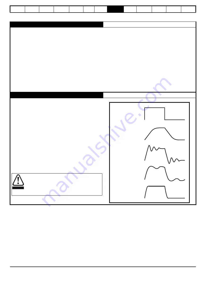
matches the ideal response shown aside.
The diagram below shows the effect of incorrect P and I gain settings as
well as the ideal response.
If the speed loop I gain (Pr
3.11
) is set to zero and later
increased, a large output transient will result causing the
drive to accelerate under full current.
The over speed trip threshold (Pr
3.08
) must be set to a
suitable level to prevent the output from reaching a level
where mechanical damage could result.
WARNING
Speed demand
Insufficient proportional
gain [
0.07
]
Excessive proportional
gain [
0.07
]
Excessive integral gain
[
0.08
]
Ideal response
Summary of Contents for Unidrive 1 Series
Page 208: ......


