3. Hardware Setup
User’s Manual
17
Installation Requirements
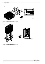
The BOX-PC can be installed in any orientation
Ο
. Avoid orientation x’s installation *1 since it might
not adequately dissipate heat. Similarly, to maintain the operating temperature within the range
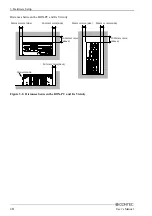
specified in the specifications, ensure a clearance between the unit and surrounding equipment of at least
100mm for the top and rear and 50mm for the bottom and sides. (Meet these requirements even with
the IPC-POAW/10-01 (option) connected.)
*1 Do not install the system unit with the heat sink upside down, on the ceiling, or with the HDD unit
slot (left-side cover) blocked by the wall.
Installation Orientation
(Connector side)
Left-side face blocked
On the ceiling
Top face positioned vertically
Upside down
USB
SERIAL2
LNK
ACT
LAN2
SERIAL1
PCMCIA
ACT
LNK
LAN1
SPD
AC C ESS
P WR
RAS
DC-IN
RST
FG V- V+
KB
DVI
SPK
AC
C
E
SS
V-
FG
V
+
DC
-IN
RS
T
SP
D
RA
S
LN
K
PC
M
C
IA
PW
R
LAN
1
LN
K
AC
T
AC
T
LA
N
2
SE
RI
A
L
2
KB
S
PK
DVI
US
B
SE
RI
A
L
1
V+
DC
-IN
FG
V-
RS
T
SP
D
SP
K
KB
LA
N
2
PW
R
AC
CE
SS
RA
S
PCM
C
IA
LA
N
1
LN
K
L
N
K
ACT
DV
I
US
B
SE
R
IA
L2
AC
T
SE
R
IA
L1
V+
RST
SPK
RA
S
US
B
SE
R
IA
L
1
PW
R
A
CC
ES
S
SP
D
DVI
PCM
C
IA
LN
K
SE
R
IA
L
2
ACT
LA
N
2
DC
-I
N
LN
K
AC
T
LAN
1
SERIAL2
SERIAL1
A CC ESS
LNK
LAN1
ACT
LNK
USB
ACT
LAN2
PWR
RAS
DVI
PCMCIA
V +
V -
FG
D C -I N
RST
SPK
S PD
KB
RA S
AC
CE
SS
RS
T
KB
SP
K
V-
FG
V
+
LA N
1
AC
CE
SS
RAS
DC-I
N
SP
D
V-
FG
KB
LNK
PWR
PCM
CIA
DV I
LAN2
LNK
AC
T
ACT
US B
SER
IA
L2
SER
IA
L1
V+
RST
SPK
SPD
DC
-IN
FG
V-
KB
LAN1
LN K
PWR
PCM
CIA
DVI
LAN
2
ACT
L N
K
USB
ACT
SE R
IAL
2
SE R
IAL
1
LNK
ACT
SERIAL2
SERIAL1
USB
AC T
LNK
LAN2
LAN1
PCMCI A
DVI
RAS
AC CE SS
P WR
KB
SPK
RST
SPD
FG V- V+
DC-IN
Figure 3.7. Installation Orientation

