background image

4. BIOS Setup


42

User’s Manual

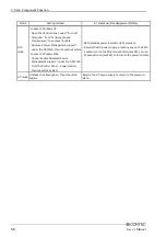
Description

Choice

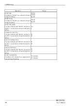
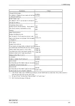
LPT & COM

This item is not used for the module.  Use the module
with this item set to "LPT/COM" by default.

NONE
LPT
COM
LPT/COM

HDD & FDD

The default is "ON"; you usually do not have to
change this setting.

OFF
ON

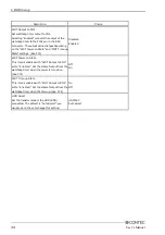
PCI Master

The default is "OFF"; you usually do not have to
change this setting.

OFF
ON

Power-On by PCI card

The default is "Disabled"; you usually do not have to
change this setting.

Disabled
Enabled

Wake Up On LAN/Ring

Enable or disable the LAN to turn the power on with
Windows in the sleep/hibernate/shutdown state.
(Dedicated to ATX mode.  See P56)  *1

Disabled
Enabled

RTC Alarm Resume

If this item is set to "Enabled," the RTC (realtime
clock) alarm can be used to specify the date and time
at which to resume from suspend mode or restart the
system.

Disabled
Enabled

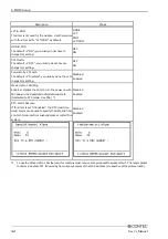
*1

To use the Wake Up On LAN feature, this machine must receive a magic packet to awaken itself.  The magic packet
contains six bytes of FF followed by 16 contiguous copies of the MAC address (irrespective of the protocol used).

Summary of Contents for IPC-BX/M360C

Page 1: ...IPC Series BOX PC for IPC BX M360 PCI C User s Manual CONTEC CO LTD...

Page 2: ...nt issues have been considered in the preparation of this document Should you notice an omission or any questionable item in this document please feel free to notify CONTEC CO LTD Regardless of the fo...

Page 3: ...EW 5 Specifications 5 System Configuration 8 External Dimensions 9 3 HARDWARE SETUP 11 Before Using the BOX PC for the First Time 11 Hardware Setup 12 Removing the Left side Cover and HDD Bracket 12 L...

Page 4: ...Without Saving 50 POST Messages 51 POST Beep 51 Error Messages 52 5 EACH COMPONENT FUNCTION 55 Component Identification 55 Line out Interface 57 Keyboard Mouse Interface 57 Serial Port Interface 58 US...

Page 5: ...iv User s Manual...

Page 6: ...small size system unit 146 W x 157 D x 64 H Fan less operation achieved by natural air cooling High reliability and completely silent running when fitted with the PC SDD V series silicon disk from CO...

Page 7: ...his device is returned freight prepaid with a copy of the original invoice and a Return Merchandise Authorization to the distributor or the CONTEC group office from which it was purchased This warrant...

Page 8: ...r applications that require a very high level of reliability Do not use the product in such applications If using this product in applications where safety is critical such as in railways automotive o...

Page 9: ...clock and CMOS RAM are backed by a Lithium primary battery The backup time at a temperature of 25 C with the power disconnected is 10 years or more Replacement of expendables is handled as a repair th...

Page 10: ...or silicon disk drive 1 internal unit IDE HDD I F Secondary Equipped with a dedicated 36pin half pitch connector for connection of an optional CD ROM left surface Serial I F RS 232C general purpose 2c...

Page 11: ...ged No more memory can be added 2 The interface can connect the PC to a CONTEC Panel Link input type display using an optional cable or an ordinary analog RGB input display using the bundled DVI analo...

Page 12: ...z directions JIS C0040 compliant IEC68 2 6 compliant Vibration resistance 8 When the HDD is not in operation when deenergized 10 57Hz semi amplitude 0 15mm 57 150Hz 2 0G 40 min each in x y and z dire...

Page 13: ...ter FD drive CF Card HDD Power unit IPC POAW 10 01 Option USB2 0 1 1 LINE OUT RST Switch 6pin mini DIN cable Keyboard mouse distribution cable SERIAL port Using the bundled cable of IPC POAW 10 01 to...

Page 14: ...120 13 13 Maximum tapping length 5mm M4 TAP 49 4 22 4 79 2 18 64 28 18 M3 TAP Maximum tapping length 5mm LNK SERIAL2 LAN2 ACT SERIAL1 PCMCIA LNK ACT LAN1 SPD DC IN ACCESS PWR RAS USB DVI RST V FG V S...

Page 15: ...mum tapping length 5mm 9 M4 TAP 10VDC OUT V N L FG V PCMCIA LAN2 SERIAL1 ACT SERIAL2 USB LNK ACT LNK LAN1 DC IN FG V V KB DVI ACCESS PWR SPD RAS SPK RST M4 TAP Maximum tappinglength 5mm mm 120 134 18...

Page 16: ...ng that you have correctly followed steps 1 and 2 turn on the power If you feel something is wrong after turning on the power turn off the power immediately and check to see if the BOX PC has been set...

Page 17: ...bracket 4 Insert the hard disk unit silicon disk drive as illustrated below and attach the left side cover Attachment position adjustment hole 1 HDD or SDD Figure 3 2 Removing and attaching the left s...

Page 18: ...JP1 CN5 Figure 3 3 Locations and Settings of Jumpers Connectors and Switches inside the Top Cover Table 3 1 Jumper List Name Function Factory setting Reference page JP1 Sets RS 485 termination Open 78...

Page 19: ...the IPC BX M360 PCI C 1 Check that the power unit s SW is turned to be OFF 2 Connect the DC cable of power unit to the power connector on the computer itself 3 Fasten the DC cable with its built in s...

Page 20: ...CI C normally MC1 5 3STF 3 81 bundled 28 to 16AWG Figure 3 5 Connection with power cable connector in use Installation method The system unit can be installed in one of the orientations in 1 to 3 belo...

Page 21: ...mm 2 LAN2 ACT SERIAL2 SERIAL1 DC IN PCMCIA LNK ACT LAN1 LNK RAS SPD PWR ACCESS USB DVI FG V V RST KB SPK 120 146 5 82 102 10 Figure 3 6 Installation method 2 3 Connector side 5 16 R5 5 R2 5 3 mm 10 82...

Page 22: ...p face positioned vertically Upside down USB SERIAL2 LNK ACT LAN2 SERIAL1 PCMCIA ACT LNK LAN1 SPD ACCESS P WR RAS DC IN RST FG V V KB DVI SPK A CC E SS V FG V DC IN RST SPD RAS LNK PCMCIA PWR LAN1 LNK...

Page 23: ...more side 50mm or more back 50mm or more side 50mm or more side USB SERIAL1 SERIAL2 LNK ACT LAN2 KB PCMCIA LNK LAN1 ACT DC IN DVI SPD RAS ACCESS PWR SPK RST V V FG RST DC IN V FG V SPD ACCESS RAS PWR...

Page 24: ...n on the system power supply the BOX PC displays the following initial screen as long as the system is normal Press the DEL key at the keyboard Phoenix AwordBIOS v6 00PG An Energy Star Ally Copyright...

Page 25: ...ase the numeric value or make changes PgDn key Decrease the numeric value or make changes key Increase the numeric value or make changes key Decrease the numeric value or make changes Esc key Main Men...

Page 26: ...4 BIOS Setup User s Manual 21 Note on the setup Information in this chapter is subject to change without notice Figure 4 2 Main window...

Page 27: ...your system Advanced BIOS Features This section allows you to configure your system for basic operation Advanced Chipset Features Use this menu to set up some features of the chipset Integrated Periph...

Page 28: ...OM Standard CMOS Setup Date mm dd yy Thu Jan 1 2001 Time hh mm ss 10 22 30 IDE Primary Master None IDE Primary Slave None IDE Secondary Master None IDE Secondary Slave None Halt On All But keyboard Ba...

Page 29: ...allowed Set to None IDE Secondary Master None Auto Manual Usually set this item to None If you have connected a CD ROM drive to the secondary IDE connector set this to Auto or Manual as required IDE S...

Page 30: ...Defaults F7 0 timized Defaults Figure 4 4 Advanced BIOS Features Window factory setting Virus Warning If you enable this feature a warning message is displayed when a program a virus in particular at...

Page 31: ...F connector on the system unit 1 IDE connection HDD 2 3 Not available USB FDD CDROM HDD Device connecting to the USB LAN For boot up from a network 2 HDD 0 CDROM HDD 1 HDD 2 HDD 3 USB FDD USB CDROM US...

Page 32: ...ery time the system boots or only when you enter setup Select whether the password be requested whenever the system boots up or only upon startup of Setup The default is Setup you usually do not have...

Page 33: ...Description Choice OS Select For DRAM 64MB The default is Non OS2 you usually do not have to change this setting Non OS2 OS2 Video BIOS Shadow The default is Enabled you usually do not have to change...

Page 34: ...IOS CMOS Setup Utility Advanced Chipset Features Item Help Menu Level Move Enter Select PU PD Values F10 Save Esc Exit F1 General Help F5 Previous Values F6 Fail Safe Defaults F7 0 timized Defaults Fi...

Page 35: ...have to change this setting 2 5 2 Precharge to Active Trp This item is disabled with DRAM Timing set to By SPD You usually do not have to change this setting 2T 3T Active to Precharge Tras This item i...

Page 36: ...oice AGP Aperture Size MB The default is 64M you usually do not have to change this setting 256M 16M 128M 8M 64M 4M 32M AGP Driving Control The default is Auto you usually do not have to change this s...

Page 37: ...indow factory setting Description Choice CPU to PCI Write Buffer The default is Enabled you usually do not have to change this setting Disabled Enabled PCI Master 0 WS Write The default is Enabled you...

Page 38: ...pe SVGA or XGA of the FPD is automatically identified with the serial signal COM of the FPD at startup If no FPD is connected or the FPD connected is left off the module enters the CRT mode providing...

Page 39: ...4 Disabled Enabled WDT Power on State This item is enabled with WDT Output to PO2 set to Enabled Set the state of output from the watchdog timer when the power is turned on See P74 Off On WDT Time up...

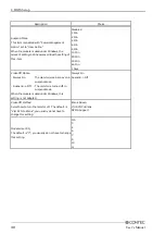
Page 40: ...ls on each item see the corresponding menu given below VIA OnChip IDE Device Phoenix AwardBIOS CMOS Setup Utility VIA OnChip IDE Device Item Help Menu Level Onchip IDE Channel0 Enabled Onchip IDE Chan...

Page 41: ...Master Slave PIO The default is Auto you usually do not have to change this setting Auto Mode 0 Mode 1 Mode 2 Mode 3 Mode 4 Secondary Master Slave PIO The default is Auto you usually do not have to ch...

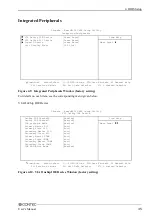
Page 42: ...e or disable the audio feature Auto Disabled OnChip USB Controller Enable or disable the USB port All Disabled 1 3 USB Port All Enabled 1 USB Port 1 2 USB Port OnChip 2 0 controller Enable or disable...

Page 43: ...Selecting 3F8 IRQ4 assigns the port to COM1 Selecting 2F8 IRQ3 assigns the port to COM2 Selecting 3E8 IRQ4 assigns the port to COM3 Selecting 2E8 IRQ3 assigns the port to COM4 in Windows Disabled 3F8...

Page 44: ...F5 Previous Values F6 Fail Safe Defaults F7 0 timized Defaults Figure 4 13 Power Management Setup Window factory setting Description Choice ACPI function The default is Disabled you usually do not ha...

Page 45: ...40 Min 1 hour Video Off Option Always On The monitor remains on even in suspend mode Suspend Off The monitor is turned off in suspend mode When the module is used under Windows this setting is not ad...

Page 46: ...tory setting Description Choice PS2KB Wakeup Select This item is not used for the module Use the module with this item set to Hot key by default Hot key Password PS2KB Wakeup from S3 S4 S5 This item i...

Page 47: ...this setting Disabled Enabled Wake Up On LAN Ring Enable or disable the LAN to turn the power on with Windows in the sleep hibernate shutdown state Dedicated to ATX mode See P56 1 Disabled Enabled RT...

Page 48: ...o not have to change the setting from the default When an I O devices requires servicing by the operating system the I O device generates an IRQ to send the signal When the operating system is ready f...

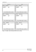
Page 49: ...4 BIOS Setup 44 User s Manual Description Choice Figure 4 15 IRQs Activity Monitoring Window factory setting...

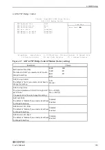
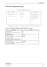
Page 50: ...ts Select Yes if you are using a Plug and Play capable operating system Select No if you need the BIOS to configure non boot devices Figure 4 16 PnP PCI Configuration Setup Window factory setting Desc...

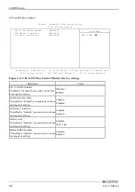
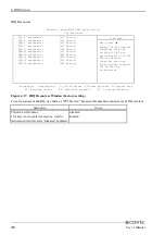
Page 51: ...I Device Move Enter Select PU PD Values F10 Save Esc Exit F1 General Help F5 Previous Values F6 Fail Safe Defaults F7 0 timized Defaults Legacy ISA for devices compliant with the original PC AT bus sp...

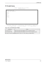
Page 52: ...s F6 Fail Safe Defaults F7 0 timized Defaults Phoenix AwardBIOS CMOS Setup Utility PC Health Status Figure 4 18 PC Health Status Window Description Choice Current CPU Temp Displays the temperature det...

Page 53: ...Spread Spectrum This item is not used for the module Use the module with this item set to Disabled by default Disable Enable Load Fail Safe Defaults When you press Enter on this item you get a confirm...

Page 54: ...nter a password To disable a password just press Enter when you are prompted to enter the password A message will confirm the password will be disabled Once the password is disabled the system will bo...

Page 55: ...ter you turn your system off The next time you start up your computer the BIOS configures your system according to the value stored in CMOS EEPROM After saving the values the system is restarted again...

Page 56: ...hing to fix it will either sound a beep code or display a message POST Beep The BIOS reports errors using two types of beeps when they cannot be reported with on screen messages One is a long beep fol...

Page 57: ...drive from which to boot the system Check whether a bootable device has been connected and whether the connectors and cables have been plugged correctly Error encountered initializing hard drive Error...

Page 58: ...ty error at Memory verify error at Memory test fail These error messages appear when system memory is abnormal They may appear when a BIOS Setup value is abnormal Run BIOS Setup again if possible Pres...

Page 59: ...OS Setup 54 User s Manual BIOS ROM checksum error System halted BIOS ROM data is invalid This message appears for example when an attempt to upgrade the BIOS has failed BIOS ROM must be removed for re...

Page 60: ...K KEYBOARD Keyboard connector MINI DIN 6pin SERIAL1 Serial port 1 connector 9pin male D SUB SERIAL2 Serial port 2 connector 9pin male D SUB USB USB port connector LAN1 LAN2 Ethernet connector RJ 45 PC...

Page 61: ...en reboot the system In case of Windows 2000 Check Enable Advanced Power Management support under the APM tab from the Control Panel Power Option then reboot the system SPD standby power indicator LED...

Page 62: ...e to download the audio driver IPC SLIB 01 for the OS running on your BOX PC For the download see Chapter 6 List of Options Keyboard Mouse Interface The BOX PC is equipped with a keyboard connector na...

Page 63: ...see the relevant page 1 The serial ports are set as follows by default SERIAL1 RS232C SERIAL2 TouchPanel To use Serial Port 2 run BIOS Setup to set Serial2 Select in the Advanced Chipset Features menu...

Page 64: ...eceive buffer register RBR 03F8H 1 W Divisor latch register LSB DLL 1 W Divisor latch register MSB DLM 03F9H 0 W Interrupt enable register IER 03FAH X R Interrupt ID register IIR 03FBH X W Line contro...

Page 65: ...read received data from 03F8H DLL Divisor Latch LSB DLAB 1 D7 D6 D5 D4 D3 D2 D1 D0 bit7 MSB bit0 LSB Baud rate setting register LSB 03F8H D7 D6 D5 D4 D3 D2 D1 D0 bit7 MSB bit0 LSB Baud rate setting re...

Page 66: ...e receiving buffer is read Generated when the transmitter holding register is empty Cleared when the IIR is read or when transmitted data is written to THR Modem status interrupt is generated CTS DSR...

Page 67: ...oop back test 0 Disable 1 Enable LSR Line Status Regester 03FDH D7 D6 D5 D4 D3 D2 D1 D0 0 TEMT THRE BI FE PE OE DR Data ready 1 for existence of received data Overrun error 1 for occurrence of an erro...

Page 68: ...is set by software by dividing the clock input 1 8432MHz The baud rate in terms of hardware can be set to a maximum of 115 200 bps The baud rates available in practice depend on the operating environ...

Page 69: ...starting of MS DOS 2 The total current capacity of four channels of USB connectors is 1 A or less Although the maximum current capacity per channel is 500 mA configure the devices such that the total...

Page 70: ...ernet Connector Connector type RJ 45 Pin No 1 2 3 4 5 6 7 8 Signal name TD TD RD N C N C RD N C N C Meamimg Transmitted data Transmitted data Received data Not connected Not connected Received data No...

Page 71: ...nd Locations Attaching the Metal Brace to Keep the Card in Place Bind screws M3 x 6 Bundled Figure 5 3 Attaching the Metal Brace to Keep the Card in Place Power Supply to the Card The voltage that can...

Page 72: ...20 TXD 9 DATA1 21 RXD 10 DATA1 22 DATA0 SHIELD 11 DATA1 SHIELD 23 CLK 12 N C 24 CLK 1 To use a CONTEC panel display select Touch Panel to the Serial2 Select in the Advanced Chipset Features menu or t...

Page 73: ...apter Connector type DVI I 29pin 1 8 17 24 16 C1 C2 C3 C4 C5 5 1 6 10 11 15 15 00 mm 6 20 5 80 39 40 30 00 33 00 Analog RGB signals Pin No Signal name Pin No Signal name 1 RED 9 HPD 2 GREEN 10 GND 3 B...

Page 74: ...600 12 inch TFT with a panel mounting touch panel IPC DT L40S PC T Panel link SVGA 800 x 600 12 inch TFT with built in touch panel IPC DT L65SVT DC1 Analog RGB DVI SVGA 800 x 600 IPC DT H61XT DC1 IPC...

Page 75: ...e with a touch panel when an LCD equipped with a touch panel is used 1 Visit the CONTEC web site to download the Touch Panel driver IPC SLIB 01 for the OS running on your BOX PC For the download see C...

Page 76: ...round RS 485 transmitting line RS 485 receiving line Minus common dedicated to PO2 General purpose output or watchdog timer alarm output General purpose output General purpose output minus common Gene...

Page 77: ...ue setting for the WDT counter port 4003h The watchdog timer stops by reading port 4002h The alarm out output is cancelled at the same time The alarm out is output from the RAS connector s PO2 WDT 12...

Page 78: ...O BIOS setting Power ON Instruct WDT to stop Set timer value Start clear WDT Modify timer value Set event output control Application To modify the timer value during operation the WDT needs to be stop...

Page 79: ...1 Table 5 15 WD_S1 WD_S0 Alarm out Output Status Settings External alarm output status WD_S1 2 WD_S0 3 When power is turned off When BIOS starts When WDT starts When time expires on WDT 0 0 OFF OFF OF...

Page 80: ...ut to IRQ5 when time expires on the WDT 0 1 1 Output to IRQ7 when time expires on the WDT 1 0 0 Output to IRQ9 when time expires on the WDT 1 0 1 Output to IRQ10 when time expires on the WDT 1 1 0 Out...

Page 81: ...it2 fixed Input protection circuit Equipped with a reverse connection protection diode Input response time Less than 100 sec External circuit power supply 12 to 24VDC 10 Output Output specifications O...

Page 82: ...IRQ 14 interrupt input 0 0 0 Inhibit the RAS connector s PI2 IRQ 14 signal interrupt to be set 0 0 1 Input the RAS connector s PI2 IRQ 14 signal to NMI 0 1 0 Input the RAS connector s PI2 IRQ 14 sign...

Page 83: ...ntrol Port 4006h TE_SEL Select the RS 485 transmission enable signal 0 Sets the RTS signal to the RS 485 transmission enable signal factory setting 1 Sets the TE_GATE value to the RS 485 transmission...

Page 84: ...eceiving permitted RE_GATE 1 Receiving prohibited VCC TXD 47k 6 2k RXD 6 2k 47k 1 2 JP1 0 1 R D Figure 5 15 Full Duplex Connection Method External I O Circuit 4 7k 1 4W External power 12V to 24VDC Inp...

Page 85: ...ndled hard disk bracket Table 5 20 Primary IDE Connector Pin No 1 3 5 7 9 11 13 15 17 19 21 23 25 27 29 31 33 35 37 39 41 43 RESET Signal DD7 DD6 DD5 DD4 DD3 DD2 DD1 DD0 GND DDRQ DIOW DIOR IOCHRDY DDA...

Page 86: ...Signal name Direction Pin No Signal name Direction 1 RESET Output 19 DDRQ Input 2 GND 20 GND 3 DD7 I O 21 DIOW Output 4 DD8 I O 22 GND 5 DD6 I O 23 DIOR Output 6 DD9 I O 24 GND 7 DD5 I O 25 IOCHRDY I...

Page 87: ...W Output 11 GND 36 5V 12 GND 37 INTRQ Input 13 5V 38 5V 14 GND 39 CSEL Output 15 GND 40 N C 16 GND 41 RESET Output 17 GND 42 IOCHRDY Input 18 DA2 Output 43 DDRQ Input 19 DA1 Output 44 DDACK Output 20...

Page 88: ...0000000 Expansion memory area Main BIOS 128KB Expansion ROM area Free to the user VGA BIOS 64KB Video RAM area 128KB RAM 640KB Reserved for BIOS 00D8000 00D7FFF 1 When First Second Third Boot Device...

Page 89: ...controller 2 master 0E0 to 0FF Reserved for system 100 to 16F Available to user 170 to 17F IDE hard disk controller Secondary 180 to 18F Reserved for system 190 to 1DF Available to user 1E8 to 1EF Re...

Page 90: ...rks NMI High I O CHECK 02H IRQ0 MASTER Timer 0 08H IRQ1 Keyboard 09H IRQ2 Interrupt controller 2 slave 0AH IRQ8 SLAVE Real time clock 70H IRQ9 ACPI 71H IRQ10 Reserved for PCI device 72H LAN2 USB IRQ11...

Page 91: ...be installed on this model HDD SDD installed models can accept an additional HDD SDD CF Card CF 512MB 512MB CompactFlash for Fix Disk CF 1GB R 1GB CompactFlash for Fix Disk CF 2GB R 2GB CompactFlash f...

Page 92: ...ktop wall mounted IPC DT L440 PC TB 12 1inch 800 x 600 dots Desktop wall mounted anti glare type Analog RGB types IPC DT M20V PC T 10 4inch 640 x 480 dots 1 IPC DT L20S PC T 12 1inch 800 x 600 dots 1...

Page 93: ...ndled cable cannot be used Purchase a dedicated cable IPC CDC 03 separately Supported OS Windows XP 2000 3 If your BOX PC is an OS preinstalled model the driver is supplied with the OS or already inst...

Page 94: ...a ku Osaka 555 0025 Japan Japanese http www contec co jp English http www contec com Chinese http www contec com cn No part of this document may be copied or reproduced in any form by any means withou...

Reviews: