5. Each Component Function
58
User’s Manual
Serial Port Interface
Serial port 1, 2(RS-232C port)
The BOX-PC is equipped with two RS-232C-compliant serial port connectors (SERIAL1: Serial port 1
and SERIAL2: Serial port 2). You can use BIOS Setup (described in Chapter 4) to configure an I/O
address, interrupt and unused state for each of the ports independently. (The same I/O address and IRQ
cannot be shared with any other device.)
Note that Serial Ports 1 and 2 are shared ports also available as the RS-422/485 and touch panel
interfaces, respectively. The interfaces sharing each serial port are mutually exclusive. *1
To use the serial port for the interface other than RS-232C, see the relevant page.
*1
The serial ports are set as follows by default: SERIAL1: RS232C / SERIAL2: TouchPanel. To use Serial Port 2, run
BIOS Setup to set "Serial2 Select" in the "Advanced Chipset Features" menu to "RS232C". (See P33)
Table 5.3. Serial port 1, 2 I/O address and Interrupts
COM
I/O address
Interrupt
1
3F8h-3FFh
2
2F8h-2FFh
3
3E8h-3EFh
4
2E8h-2EFh
IRQ 3
IRQ 4
The BIOS defaults to the following factory settings:
Serial port 1: COM1(3F8h-3FFh),IRQ4
Serial port 2: COM2(2F8h-2FFh),IRQ3
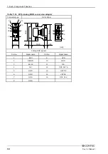
Table 5.4. Serial Port Connector
Pin No.
1
2
3
4
5
6
7
8
9
Connector used on the unit
9-socket D-SUB (MALE)
Signal name
CD
RD
TD
DTR
GND
DSR
RTS
CTS
RI
Direction
Input
Input
Output
Output
-----
Input
Output
Input
Input
Meaning
Carrier detect
Received data
Transmitted data
Data terminal ready
Signal ground
Data set ready
Request to send
Clear to send
Ring indicator
9
6
No.4-40UNC
Inch thread
1
5

