5. Each Component Function
User’s Manual
67
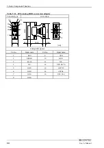
DVI Connector
This is the DVI connector for the CRT/LCD. You can use it to connect a display (even a D-SUB-15pin
connector is acceptable by using the bundled DVI-analog RGB adapter) or a CONTEC Panel Link
display *1. The pin assignments are as follows.
Table 5.11. DVI Connector
Connector type
DVI-I 29pin
1
8
17
24
16
9
C1
C2
C3
C4
C5
Pin No.
Signal name
Pin No.
Signal name
Pin No.
Signal name
1
DATA2-
13
N.C.
C1
RED
2
DATA2+
14
+5V
C2
GREEN
3
DATA2
SHIELD
15
GND
C3
BLUE
4
N.C.
16
HPD
C4
HSYNC
5
N.C.
17
DATA0-
C5
GND
6
DDC CLK
18
DATA0+
7
DDC
DATA
19
DATA0
SHIELD
8
VSYNC
20
TXD
9
DATA1-
21
RXD
10
DATA1+
22
DATA0
SHIELD
11
DATA1
SHIELD
23
CLK+
12
N.C.
24
CLK-
*1
To use a CONTEC panel display, select "Touch Panel" to the "Serial2 Select" in the "Advanced Chipset Features"
menu or the display mode of the connected display with the "Panel Type." (See P33)
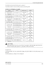
CAUTION
-
Installation of the display driver for windows sets resolution as 1024 x 7684. When you use it in
different resolution, please re-setup in the display mode before re-starting.
When it re-starts without setting up, it becomes impossible to express a screen as the monitor which
cannot display 1024 x 768.
-
The display is not guaranteed about resolution except 720 x 400, 640 x 480, 800 x 600, 1024 x 768.
There is a case where it cannot be displayed that the display mode more than the recommendation
resolution of a display is set up.

