5. Each Component Function
User’s Manual
55
5.
Each Component Function
Component Identification
POWER LED
PWR
SERIAL2
SERIAL1
LAN1
LAN2
LAN2
LAN1
USB
SERIAL2
SERIAL1
ACT
USB
LNK
ACT
LNK
PCMCIA
DVI
10VDC-IN
RAS
DC-IN
FG V- V+
STANDBY POWER LED
KB
RAS
DVI
ACCESS
SPD
SPK
RST
ACCESS LED
KEYBOARD
PCMCIA
LINE OUT
RESET
< Left side >
HDD
SECONDARY IDE
CF Slot
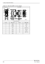
Figure 5.1. Component Identification
Table 5.1. Component Identification
Name
Function
LINE OUT
Line out (
φ
3.5 PHONE JACK)
KEYBOARD
Keyboard connector (MINI-DIN, 6pin)
SERIAL1
Serial port 1 connector (9pin, male D-SUB)
SERIAL2
Serial port 2 connector (9pin, male D-SUB)
USB
USB port connector
LAN1, LAN2
Ethernet connector (RJ-45)
PCMCIA
PCMCIA card slot
DVI
DVI connector (29pin, DVI-I)
RAS
RAS function (9pin, female D-SUB)
RESET
Hard reset push button
POWER LED
Power ON indicator
ACCESS LED
Internal hard disk access lamp
STANDBY POWER LED
Stand by Power LED (Dedicated to ATX mode, coming on at shutdown) *1
SECONDARY IDE
Secondary IDE connector (dedicated 36pin half-pitch connector)
CF Slot
CF Card Slot(Secondary IDE connection)
*1
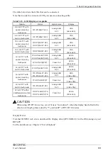
See the list of the next page for differences between ATX and AT modes.


