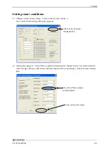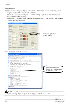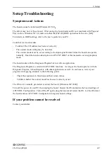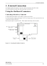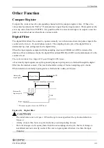
3. External Connection
CNT24-4(PCI)H
31
Interface connector for the TTL-level input(CN2)
- Connector used
PS-30PE-D4T1PN1(made by JAE) or equivalent to it
- Applicable connector
PS-30SEN-D4P1-1C (made by JAE)
B15 B14 B13
A3 A2 A1
A15 A14 A13
B3 B2 B1
Figure 3.4. Connector used(CN2)
B1
B2
B3
B4
B5
B6
B7
B8
B9
B10
B11
B12
B13
B14
B15
Not Connected
General-purpose Input
Phase-Z / CLR
Phase-B / DOWN
Phase-A / UP
Ground
General-purpose Input
Phase-Z / CLR
Phase-B / DOWN
Not Connected
General-purpose Input
Phase-Z / CLR
Phase-B / DOWN
Phase-A / UP
+5V*2
CH0
N.C.
T1U
T1Z
T1B
T1A
GND*1
T0U
T0Z
T0B
N.C.
T3U
T3Z
T3B
T2A
Vcc*1
A1
A2
A3
A4
A5
A6
A7
A8
A9
A10
A11
A12
A13
A14
A15
T0A
N.C.
GND*1
GND*1
GND*1
GND*1
GND*1
GND*1
GND*1
T3A
GND*1
T2U
T2Z
T2B
Vcc*1
Phase-A / UP
Not Connected
Ground
Ground
Ground
Ground
Ground
Ground
Ground
Phase-A / UP
Ground
General-purpose Input
Phase-Z / CLR
Phase-B / DOWN
+5V*2
CH1
CH3
CH2
CH0
CH2
CH3
*1: The VCC and GND signals are all common.
The maximum current flowing through these two Vcc pins together is 500mA.
*2: O5V power supplied from the +5V pin in the PC to the external device.
Use this pin to 5V power to an external device (such as an encoder) for simple checking.
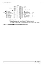
Figure 3.5. Pin Assignment of an interface connector(CN2)
30 pin connector
(Connect to the CN2)
37 pin D-SUB connector
(Connect to the external device)
* 37 pin D-SUB connector is the same as with the CN1.
37
20
19
1
36
18
21
2
Figure 3.6. Optional Cable DT/B2


