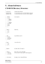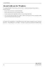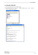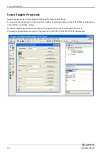
4. Function
42
CNT24-4(PCI)H
Asynchronous Clear
If a counter is set for CW (clockwise) direction Up-count and phase-Z positive logic, whenever the
phase-Z input goes high will reset the count value no matter which signal level the phase-A and phase-
B is. The counter will start counting from next rising edge of the phase-A no matter what signal level the
phase-Z is.
2
3
1
1
0
Phase-A
(Phase-A/UP)
Phase-B
(Phase-B/DOWN)
Phase-Z
(Phase-Z/CLR)
Count value
* When incremental counting in the CW direction is set with phase-Z positive logic,
the board performs decremental counting at the rising edge of the phase-A signal
while the phase-B input remains low. When phase-Z negative logic is used,
the signal is enabled while the phase-Z input remains low.
Figure 4.6. Example counting during asynchronous clear
Phase Z/CLR Input
Phase-Z is the signal to clear the counter to zero. The number of phase-Z inputs can be specified by
software.
Phase-Z input
Disable phase-Z input
Counter 0 Ignored
Phase-Z input
Enable the next phase-Z input only once
Counter 0
0
Start
Phase-Z input
Enable every phase-Z input
Counter 0
0
Start
0
0
0
Ignored
Ignored
Ignored
Ignored
Ignored
Ignored
Figure 4.7. Phase-Z enable frequency(Positive logic)
CAUTION
-
The default setting is “only the next phase-Z input is enabled once”.
-
If phase-Z is set as negative logic, a valid signal of phase-Z input is low level.
-
If the phase-Z/CLR input is not used, be sure to set the phase-Z to “disable the phase-Z input.”

